Activity 2. Read Serial Data
In this activity the Arduino Uno reads data from the serial communication and performs actions according to the commands it has read. More specifically, the Arduino Uno works as an up / down-counter that counts from 0 to 9 every 500ms. The numbers are shown in a 7 segment display. Setting the counter to count up or down is done by serial communication.
Activity 2
By default, the Arduino Uno works as an up-counter. It can accept 2 commands from serial communication.
Table 2. Commands from the serial communication
|
Command |
Selection |
|
“up” |
Up-counter |
|
“down” |
Down-counter |
|
Anything else is considered a wrong command |
|
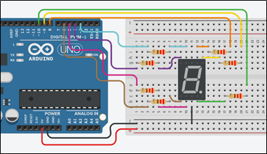
Step 1. Draw the circuit in Tinkercad.
Step 2. Study the code and write it on the microcontroller:
/* Up/down-counter and seven segment display
Circuit Connections:
Seven segment common Cathode = > Gnd
PIN_3 => Resistor 220Ω => Segment f
PIN_4 => Resistor 220Ω => Segment g
PIN_5 => Resistor 220Ω => Segment d
PIN_6 => Resistor 220Ω => Segment e
PIN_8 => Resistor 220Ω => Segment a
PIN_9 => Resistor 220Ω => Segment b
PIN_10 => Resistor 220Ω => Segment c
PIN_0 => Serial RX
PIN_1 => Serial TX
*/
#define A_pin 8 //give the name “A_pin” to PIN_8
#define B_pin 9 //give the name “B_pin” to PIN_9
#define C_pin 10 //give the name “C_pin” to PIN_10
#define D_pin 5 //give the name “D_pin” to PIN_5
#define E_pin 6 //give the name “E_pin” to PIN_6
#define F_pin 3 //give the name “F_pin” to PIN_3
#define G_pin 4 //give the name “G_pin” to PIN_4
boolean count=true; //true=up-counter, false=down-counter
String input; //variable to save data from serial
int i=0; //variable to hold the number for the seven segment display
//The setup() function initializes and sets the initial values
//It will only run once after each powerup or reset
void setup() {
pinMode(A_pin, OUTPUT); //Configure the PIN_8 to behave as output
pinMode(B_pin, OUTPUT); //Configure the PIN_9 to behave as output
pinMode(C_pin, OUTPUT); //Configure the PIN_10 to behave as output
pinMode(D_pin, OUTPUT); //Configure the PIN_5 to behave as output
pinMode(E_pin, OUTPUT); //Configure the PIN_6 to behave as output
pinMode(F_pin, OUTPUT); //Configure the PIN_3 to behave as output
pinMode(G_pin, OUTPUT); //Configure the PIN_4 to behave as output
//opens serial port, sets data rate to 9600 bps
Serial.begin(9600);
}//This function loops consecutively
void loop() {
//call the function “sevenSegment” and display the number “i”
sevenSegment(i);
delay(500); //wait for 0.5s
//check for serial data
if (Serial.available() > 0){
//read and save data
input = Serial.readString();
//check data’s value
if(input == "up"){
count=true; //up-counter
}
else if(input=="down"){
count=false; //down-counter
}
else{
Serial.println("Wrong command");
}
}
//increase (or decrease) the number and check for overflow
if (count == true){
i++;
if(i>9){
i=0;
}
}
else{
i--;
if(i<0){
i=9;
}
}
}
//This function activates and deactivates the segments
//so the numbers appear on the display
void sevenSegment (int selection){
  switch(selection){
  case 0:
  /* display 0
         -
       |  |
       |  |
         -
    */
      digitalWrite(A_pin, HIGH);              //activate segment A
      digitalWrite(B_pin, HIGH);               //activate segment B
      digitalWrite(C_pin, HIGH);              //activate segment C
      digitalWrite(D_pin, HIGH);              //activate segment D
      digitalWrite(E_pin, HIGH);               //activate segment E
      digitalWrite(F_pin, HIGH);               //activate segment F
      digitalWrite(G_pin, LOW);               //deactivate segment G
      break;

  case 1:
 /* display 1

         |
         |

    */
      digitalWrite(A_pin, LOW);                //deactivate segment A
      digitalWrite(B_pin, HIGH);               //activate segment B
      digitalWrite(C_pin, HIGH);               //activate segment C
      digitalWrite(D_pin, LOW);                //deactivate segment D
      digitalWrite(E_pin, LOW);                //deactivate segment E
      digitalWrite(F_pin, LOW);                //deactivate segment F
      digitalWrite(G_pin, LOW);                //deactivate segment G
      break;

  case 2:
  /* display 2
        -
         |
        -
       |
        -
    */
      digitalWrite(A_pin, HIGH);               //activate segment A
      digitalWrite(B_pin, HIGH);               //activate segment B
      digitalWrite(C_pin, LOW);                //deactivate segment C
      digitalWrite(D_pin, HIGH);               //activate segment D
      digitalWrite(E_pin, HIGH);               //activate segment E
      digitalWrite(F_pin, LOW);                //deactivate segment F
      digitalWrite(G_pin, HIGH);               //activate segment G
      break;

  case 3:
  /* display 3
        -
         |
        -
         |
        -
    */
      digitalWrite(A_pin, HIGH);               //activate segment A
      digitalWrite(B_pin, HIGH);               //activate segment B
      digitalWrite(C_pin, HIGH);               //activate segment C
      digitalWrite(D_pin, HIGH);               //activate segment D
      digitalWrite(E_pin, LOW);                //deactivate segment E
      digitalWrite(F_pin, LOW);                //deactivate segment F
      digitalWrite(G_pin, HIGH);               //activate segment G
      break;

  case 4:
  /* display 4

       | |
         -
         |

    */
      digitalWrite(A_pin, LOW);                //deactivate segment A
      digitalWrite(B_pin, HIGH);               //activate segment B
      digitalWrite(C_pin, HIGH);               //activate segment C
      digitalWrite(D_pin, LOW);                //deactivate segment D
      digitalWrite(E_pin, LOW);                //deactivate segment E
      digitalWrite(F_pin, HIGH);               //activate segment F
      digitalWrite(G_pin, HIGH);               //activate segment G
      break;

  case 5:
  /* display 5
        -
       |
        -
         |
        -
    */
      digitalWrite(A_pin, HIGH);              //activate segment A
      digitalWrite(B_pin, LOW);               //deactivate segment B
      digitalWrite(C_pin, HIGH);              //activate segment C
      digitalWrite(D_pin, HIGH);              //activate segment D
      digitalWrite(E_pin, LOW);               //deactivate segment E
      digitalWrite(F_pin, HIGH);              //activate segment F
      digitalWrite(G_pin, HIGH);              //activate segment G
      break;

  case 6:
  /* display 6

       |
        -
       |  |
        -
    */
      digitalWrite(A_pin, LOW);                //deactivate segment A
      digitalWrite(B_pin, LOW);                //deactivate segment B
      digitalWrite(C_pin, HIGH);               //activate segment C
      digitalWrite(D_pin, HIGH);               //activate segment D
      digitalWrite(E_pin, HIGH);               //activate segment E
      digitalWrite(F_pin, HIGH);               //activate segment F
      digitalWrite(G_pin, HIGH);               //activate segment G
      break;

  case 7:
  /* display 7
       _
         |
         |

    */
      digitalWrite(A_pin, HIGH);               //activate segment A
      digitalWrite(B_pin, HIGH);               //activate segment B
      digitalWrite(C_pin, HIGH);               //activate segment C
      digitalWrite(D_pin, LOW);                //deactivate segment D
      digitalWrite(E_pin, LOW);                //deactivate segment E
      digitalWrite(F_pin, LOW);                //deactivate segment F
      digitalWrite(G_pin, LOW);                //deactivate segment G
      break;

  case 8:
  /* display 8
         -
       |  |
         -
       |  |
         -
    */
      digitalWrite(A_pin, HIGH);               //activate segment A
      digitalWrite(B_pin, HIGH);               //activate segment B
      digitalWrite(C_pin, HIGH);               //activate segment C
      digitalWrite(D_pin, HIGH);               //activate segment D
      digitalWrite(E_pin, HIGH);               //activate segment E
      digitalWrite(F_pin, HIGH);               //activate segment F
      digitalWrite(G_pin, HIGH);               //activate segment G
      break;

  case 9:
  /* display 9
         -
       |  |
         -
          |

    */
      digitalWrite(A_pin, HIGH);              //activate segment A
      digitalWrite(B_pin, HIGH);              //activate segment B
      digitalWrite(C_pin, HIGH);              //activate segment C
      digitalWrite(D_pin, LOW);               //deactivate segment D
      digitalWrite(E_pin, LOW);               //deactivate segment E
      digitalWrite(F_pin, HIGH);              //activate segment F
      digitalWrite(G_pin, HIGH);              //activate segment G
      break;
  }
}
Step 3. Run the simulation and check the correct operation of the circuit
Step 4. Suggested modifications and discussion:
- Add commands via serial communication: start/stop counter