Activity 1. Flash a LED
The purpose of this activity is to flash a LED twice, through the interrupt service routine of RB1 (INT1).
(40 minutes)
Activity 1
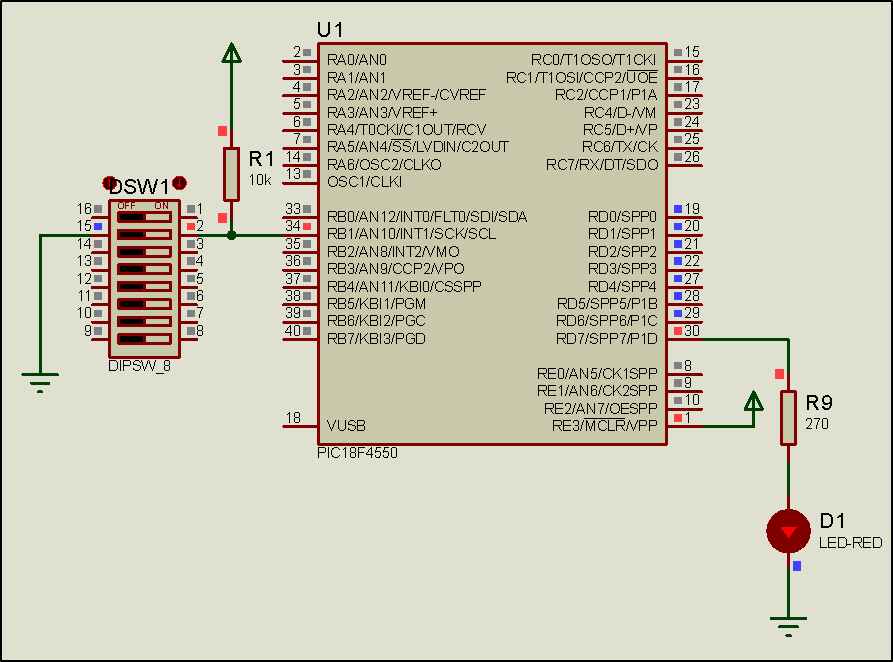
Step 1. The circuit is drawn in the Proteus Design Suite.
Step 2. The program in C language is written.
Write in CCS C Compiler the program in C language
#include <main.h> // the file main.h with the
// initial settings is included
// This file must be placed in the same
// folder with the project
// Also the 18F4550.h file must exist
// in the same folder with the project
#byte PORTD =0xF83 // We attribute to the memory position 0xF83
// the name PORTD
// This means that we define a 8 bit
// variable whose value will be stored
// to the memory position F83h
// The memory position F83h is the PORTD
// data register
void init(void);
void ext_int1(void);
void main(){
init(); //initialization routine
while(TRUE){;} //the main program does nothing
}
void init(){
set_tris_d(0x00); //PORTD is defined as output
PORTD = 0b00000000; //The PORTD data register is given the value 0
ext_int_edge(1, L_TO_H); //Activation of the interrupt from RB1
//during the transition from 0 to 1 (raising edge)
enable_interrupts(GLOBAL); //Enable global interrupts
enable_interrupts(INT_EXT1); //Enable external interrupt by RB1
}
#INT_EXT1 HIGH //External interrupt by RB1
void ext_int1(){
int i;
for(i=1;i<3; i++){ //performed twice
output_high(PIN_D7); //LED is on
delay_ms(200); //wait for 0.2s
output_low(PIN_D7); //LED is of
delay_ms(200); //wait for 0.2s
}
}Step 3. The program is compiled with the use of CCS C compiler to the microcontroller machine code.
Step 4. Load to the microcontroller the hex file (program in machine code) that was created from the CCS C Compiler.
Step 5. Run the simulation and check the correct operation of the circuit.
Step 6. Suggested modifications and discussion:
Run and
check the simulation