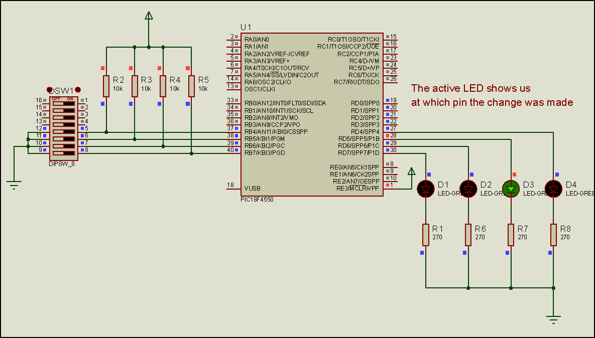
Activity 3. RB4~RB7 on change interrupt
The purpose of this activity is to handles interrupts by state changes in RB4, RB5, RB6, and RB7. When an interrupt occurs, the corresponding LED connected to the PORTD is activated.
(35 minutes)
Activity 3
Step 1. The circuit is drawn at the Proteus Design Suite.

Step 2. The program in C language is written.
Write in CCS C Compiler the program in C language
#include <main.h> // the file main.h with the
// initial settings is included
// This file must be placed in the same
// folder with the project
// Also the 18F4550.h file must exist
// in the same folder with the project
#byte PORTD =0xF83 // We attribute to the memory position 0xF83
// the name PORTD
// This means that we define a 8 bit
// variable whose value will be stored
// to the memory position F83h
// The memory position F83h is the PORTD
// data register
#byte PORTB=0xF81 // We attribute to the memory position 0xF81
// the name PORTD
// This means that we define a 8 bit
// variable whose value will be stored
// to the memory position F81h
// The memory position F81h is the PORTD
// data register
void rb(void) ; //Interrupt service routine statement (from RB4, RB5, RB6, RB7)
void init(void);
int8 lastPORTB; //Global variable to hold the last value of PORTΒ
void main(){
init(); //call the initialization routine
while(TRUE){;} //the main program does nothing
}
//initialization routine
void init(){
set_tris_d(0x00); //PORTD is defined as output
PORTD = 0b00000000; //The PORTD data register is given the value 0
lastPORTB=PORTB;
enable_interrupts(GLOBAL); //Enable global interrupts
enable_interrupts(INT_RB); //Enable change interrupt by RB4, RB5, RB6, RB7
}
//PORTB change interrupt
#INT_RB
void rb (void){
int8 changes; //Define an 8bit variable
changes = lastPORTB ^ PORTB; //The changed bit becomes 1 and appears in the corresponding position in the change variable
lastPORTB=PORTB; //The new PORTB value is transferred to the lastPORTB variable
PORTD=changes; //The changed bit is displayed in PORTD
delay_ms (100); //delay to avoid bounces
}Step 3. Compile the program in order to create the hex.file (program in machine code). Load the program (hex.file) to the microcontroller.
Step4. Run the simulation and check the correct operation of the circuit.