Activity 3. Switches and push-button
This activity uses push-button and switches that provide input signals on the Arduino Uno. The main objective is to understand the circuit wiring and the corresponding code. (45 minutes)
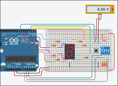
Activity 3
When the push-button is pressed and released, the Arduino Uno counts from 0 to 9 on a common cathode seven segment display. The numbers change at a rate defined by switches states, Table 2.
- The push-button is connected to PIN_7. The built-in pull-up resistor is activated with an appropriate setting in pinMode(), so no external resistor needs to be used
- A voltmeter has been added to the circuit to check the voltage at the PIN_7
Table 2. Possible states and time delay setting
|
Switch_1 |
Switch_2 |
Switch_3 |
delay_ms |
|
0 |
0 |
0 |
200 |
|
0 |
0 |
1 |
2000 |
|
1 |
1 |
0 |
400 |
|
1 |
1 |
1 |
4000 |
|
All other combinations |
500 |
||
Step 1. Draw the circuit in Tinkercad.
Step 2. Study the code and write it on the microcontroller:
/* Push button and seven segment display
Circuit Connections: Seven segment common Cathode = > Gnd PIN_0 => Resistor 220Ω => Segment a PIN_1 => Resistor 220Ω => Segment b PIN_2 => Resistor 220Ω => Segment c PIN_3 => Resistor 220Ω => Segment f PIN_4 => Resistor 220Ω => Segment g PIN_5 => Resistor 220Ω => Segment d PIN_6 => Resistor 220Ω => Segment e PIN_7 => Pull-up resistor (built in) => push-button (Gnd) PIN_A2 => Switch_1 (Vcc) PIN_A1 => Switch_2 (Vcc) PIN_A0 => Switch_3 (Vcc) */
#define A_pin 0 //give the name “A_pin” to PIN_0 #define B_pin 1 //give the name “B_pin” to PIN_1 #define C_pin 2 //give the name “C_pin” to PIN_2 #define D_pin 5 //give the name “D_pin” to PIN_5 #define E_pin 6 //give the name “E_pin” to PIN_6 #define F_pin 3 //give the name “F_pin” to PIN_3 #define G_pin 4 //give the name “G_pin” to PIN_4 #define pb_pin 7 //give the name “pb_pin” to PIN_7
boolean pressAndReleased=false; //flag for push-button int speed; //variable for delay time
//The setup() function initializes and sets the initial values //It will only run once after each powerup or reset void setup() { pinMode(A_pin, OUTPUT); //Configure the PIN_0 to behave as output pinMode(B_pin, OUTPUT); //Configure the PIN_1 to behave as output pinMode(C_pin, OUTPUT); //Configure the PIN_2 to behave as output pinMode(D_pin, OUTPUT); //Configure the PIN_5 to behave as output pinMode(E_pin, OUTPUT); //Configure the PIN_6 to behave as output pinMode(F_pin, OUTPUT); //Configure the PIN_3 to behave as output pinMode(G_pin, OUTPUT); //Configure the PIN_4 to behave as output //Configure PIN_7 to behave as input with activated pull-up resistor pinMode(pb_pin, INPUT_PULLUP);//Configure PIN_A0, PIN_A1 and PIN_A2 to behave as inputs pinMode(sw1_pin, INPUT); pinMode(sw2_pin, INPUT); pinMode(sw3_pin, INPUT); }
//This function loops consecutively void loop() { //check switches for speed settings if (digitalRead(sw1_pin)==0 && digitalRead(sw2_pin)==0){ speed=200; if(digitalRead(sw3_pin)==1){ speed=2000; } } else if(digitalRead(sw1_pin)==1 && digitalRead(sw2_pin)==1){ speed=400; if(digitalRead(sw3_pin)==1){ speed=4000; } } else{ speed=500; }
if (digitalRead(pb_pin)==0){ //push-button pressed delay(25); //debounce while(digitalRead(pb_pin)==0){;} //push-button released delay(25); //debounce //set the flag to true pressAndReleased=true; } //check the flag for push-button press and release if (pressAndReleased == true){ //call the function “sevenSegment” and display the numbers from 0 to 9 for (int i=0; i<10; i++){ sevenSegment(i); delay(speed); //wait for “speed” milliseconds } //set the flag to false pressAndReleased=false;
//deactivate every segment digitalWrite(A_pin, LOW); digitalWrite(B_pin, LOW); digitalWrite(C_pin, LOW); digitalWrite(D_pin, LOW); digitalWrite(E_pin, LOW); digitalWrite(F_pin, LOW); digitalWrite(G_pin, LOW); } }
//This function activates and deactivates the segments
//so the numbers appear on the display
void sevenSegment (int selection){
  switch(selection){
  case 0:
  /* display 0
         -
       |  |
       |  |
         -
    */
      digitalWrite(A_pin, HIGH);              //activate segment A
      digitalWrite(B_pin, HIGH);               //activate segment B
      digitalWrite(C_pin, HIGH);              //activate segment C
      digitalWrite(D_pin, HIGH);              //activate segment D
      digitalWrite(E_pin, HIGH);               //activate segment E
      digitalWrite(F_pin, HIGH);               //activate segment F
      digitalWrite(G_pin, LOW);               //deactivate segment G
      break;

  case 1:
 /* display 1

         |
         |

    */
      digitalWrite(A_pin, LOW);                //deactivate segment A
      digitalWrite(B_pin, HIGH);               //activate segment B
      digitalWrite(C_pin, HIGH);               //activate segment C
      digitalWrite(D_pin, LOW);                //deactivate segment D
      digitalWrite(E_pin, LOW);                //deactivate segment E
      digitalWrite(F_pin, LOW);                //deactivate segment F
      digitalWrite(G_pin, LOW);                //deactivate segment G
      break;

  case 2:
  /* display 2
        -
         |
        -
       |
        -
    */
      digitalWrite(A_pin, HIGH);               //activate segment A
      digitalWrite(B_pin, HIGH);               //activate segment B
      digitalWrite(C_pin, LOW);                //deactivate segment C
      digitalWrite(D_pin, HIGH);               //activate segment D
      digitalWrite(E_pin, HIGH);               //activate segment E
      digitalWrite(F_pin, LOW);                //deactivate segment F
      digitalWrite(G_pin, HIGH);               //activate segment G
      break;

  case 3:
  /* display 3
        -
         |
        -
         |
        -
    */
      digitalWrite(A_pin, HIGH);               //activate segment A
      digitalWrite(B_pin, HIGH);               //activate segment B
      digitalWrite(C_pin, HIGH);               //activate segment C
      digitalWrite(D_pin, HIGH);               //activate segment D
      digitalWrite(E_pin, LOW);                //deactivate segment E
      digitalWrite(F_pin, LOW);                //deactivate segment F
      digitalWrite(G_pin, HIGH);               //activate segment G
      break;

  case 4:
  /* display 4

       | |
         -
         |

    */
      digitalWrite(A_pin, LOW);                //deactivate segment A
      digitalWrite(B_pin, HIGH);               //activate segment B
      digitalWrite(C_pin, HIGH);               //activate segment C
      digitalWrite(D_pin, LOW);                //deactivate segment D
      digitalWrite(E_pin, LOW);                //deactivate segment E
      digitalWrite(F_pin, HIGH);               //activate segment F
      digitalWrite(G_pin, HIGH);               //activate segment G
      break;

  case 5:
  /* display 5
        -
       |
        -
         |
        -
    */
      digitalWrite(A_pin, HIGH);              //activate segment A
      digitalWrite(B_pin, LOW);               //deactivate segment B
      digitalWrite(C_pin, HIGH);              //activate segment C
      digitalWrite(D_pin, HIGH);              //activate segment D
      digitalWrite(E_pin, LOW);               //deactivate segment E
      digitalWrite(F_pin, HIGH);              //activate segment F
      digitalWrite(G_pin, HIGH);              //activate segment G
      break;

  case 6:
  /* display 6

       |
        -
       |  |
        -
    */
      digitalWrite(A_pin, LOW);                //deactivate segment A
      digitalWrite(B_pin, LOW);                //deactivate segment B
      digitalWrite(C_pin, HIGH);               //activate segment C
      digitalWrite(D_pin, HIGH);               //activate segment D
      digitalWrite(E_pin, HIGH);               //activate segment E
      digitalWrite(F_pin, HIGH);               //activate segment F
      digitalWrite(G_pin, HIGH);               //activate segment G
      break;

  case 7:
  /* display 7
       _
         |
         |

    */
      digitalWrite(A_pin, HIGH);               //activate segment A
      digitalWrite(B_pin, HIGH);               //activate segment B
      digitalWrite(C_pin, HIGH);               //activate segment C
      digitalWrite(D_pin, LOW);                //deactivate segment D
      digitalWrite(E_pin, LOW);                //deactivate segment E
      digitalWrite(F_pin, LOW);                //deactivate segment F
      digitalWrite(G_pin, LOW);                //deactivate segment G
      break;

  case 8:
  /* display 8
         -
       |  |
         -
       |  |
         -
    */
      digitalWrite(A_pin, HIGH);               //activate segment A
      digitalWrite(B_pin, HIGH);               //activate segment B
      digitalWrite(C_pin, HIGH);               //activate segment C
      digitalWrite(D_pin, HIGH);               //activate segment D
      digitalWrite(E_pin, HIGH);               //activate segment E
      digitalWrite(F_pin, HIGH);               //activate segment F
      digitalWrite(G_pin, HIGH);               //activate segment G
      break;

  case 9:
  /* display 9
          -
       |  |
          -
          |

    */
      digitalWrite(A_pin, HIGH);              //activate segment A
      digitalWrite(B_pin, HIGH);              //activate segment B
      digitalWrite(C_pin, HIGH);              //activate segment C
      digitalWrite(D_pin, LOW);               //deactivate segment D
      digitalWrite(E_pin, LOW);               //deactivate segment E
      digitalWrite(F_pin, HIGH);              //activate segment F
      digitalWrite(G_pin, HIGH);              //activate segment G
      break;
  }
}
Step 3. Run the simulation and check the correct operation of the circuit