Activity 1. Read a binary word from PORTD
The purpose of this activity is to read a binary value from PORTD and send to the PORTB the result of the read value divided by 2.
(60 minutes)
Activity 1
Step 1. The circuit is drawn in the Proteus Design Suite. In this step 8 LEDs are connected to the PORTB parallel port. 8 switches are connected to PORTD and 8 pull up resistors.
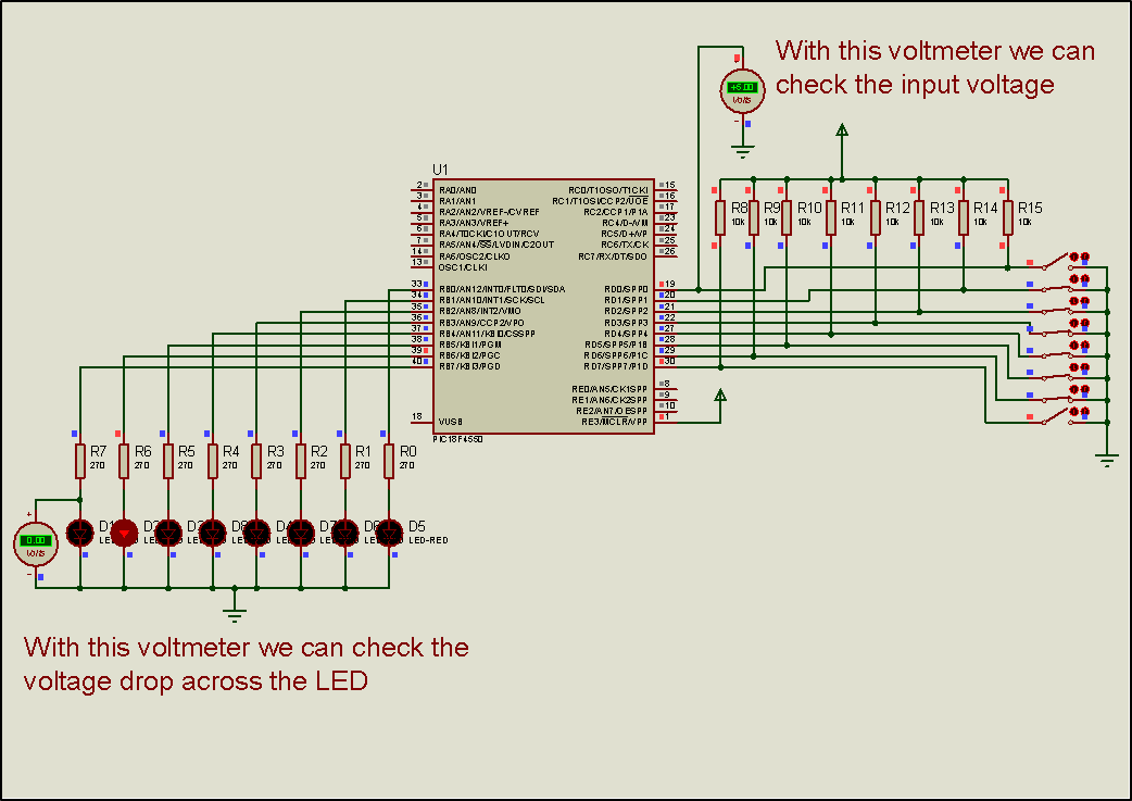
Step 2. The values of the resistors are calculated so that the current through the LEDs is 10mA. It is accepted that the voltage drop across the animated red LEDs is 2.2 V.
Step 3. The program in C language is written.
Write in CCS Compiler the program in C language
#include<main.h> // This file contains the initial settings
// It must be in the same folder with the project
#byte PORTB=0xF81 // F81 Is the position or PORTB data register
// at the data memory of the microcontroller
// SFR Special Function Register
#byte PORTD=0xF83 // F83 Is the position or PORTB data register
// at the data memory of the microcontroller
//SFR Special Function Register
// ********* Main program ************************
void main()
{ // Opening bracket of main
set_tris_b(0x00); // PORTB is set as output port
// (PORTB Direction Register = 0000 0000)
set_tris_d(0xff); // PORTD is set as input port
// (PORTD Direction Register = 1111 1111)
int8 a; //Definition of integer variable a
while(TRUE) { //Endless loop(Condition always TRUE)
a=PORTD; //Varable a takes the value or input port D
PORTB=a/2; // Output portB takes the value a/2
} //Closes the bracket of while
} // Closing bracket of main
Step 4. The program is compiled with the use of CCS C compiler to the microcontroller machine code.
Step 5. The machine code is loaded to the microcontroller.
Step 6. The animation is activated.
Step 7. We form a binary value by closing and opening the switches connected to PORTD that has been defined as input port.
- By turning on and off the switches form at PORTD the number 6. Check that the value that appears at PORTB is 3.
- By turning on and off the switches form at PORTD the value 255. Check that the value of PORTB is the expected one.
- By turning on and off the switches form at PORTD the value 1. Check that PORTB takes the expected value.
Step 8. We check
that the value of PORTB, is equal to the half to the value of PORTD
Step 7. Suggested modifications and discussion: