Exercise 6: SPI bus
SPI bus
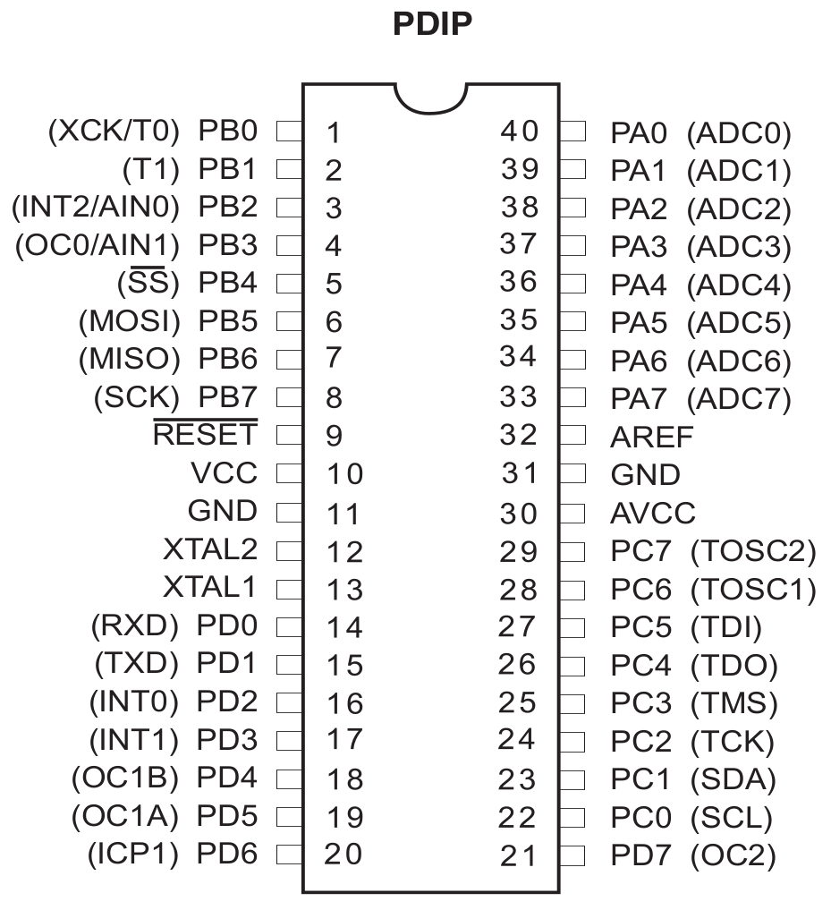
In this exercise we will use the SPI bus, the lines of which are led out on pins PB4-PB7:
In order to use the SPI bus, it is convenient to create a library containing two functions:
1. void SPI_MasterInit (void) - to initialize the SPI bus
2. uint8_t SPI_MasterTransmit (uint8_t data) - for sending and receiving data using the SPI bus.
In the first function:
- the SPI bus should be turned on,
- the Master operating mode should be selected
- the appropriate prescaler should be selected.
The following is an excerpt from the documentation for the SPCR register (SPI control register):
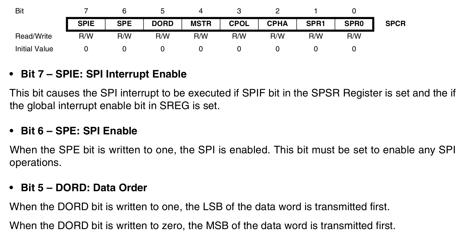

To enable the SPI bus, set 1 on the SPE bit. In turn, the MSTR bit is responsible for the selection of the operating mode. If you set it to 1, the microcontroller will work in the Master mode. However, when you set 0 on the MSTR bit, the microcontroller will work as a Slave. The selection of the prescaler depends on the slave system. Its documentation should check the maximum frequency with which it can work. On this basis, the prescaler is selected.
We will realize two activities during this exercise. First activity is connected with LED matrix (MAX7219) and second activity is based on A/D converter (MCP3202). Of the two components, the A/D converter has the smaller frequency range. So we will create a library for SPI for A/D converter. Thanks to this, the same library will be able to be used in two activities.
Based on the documentation for the A/D converter (link,
page 3), we can read that it operates at a maximum frequency of 1.8
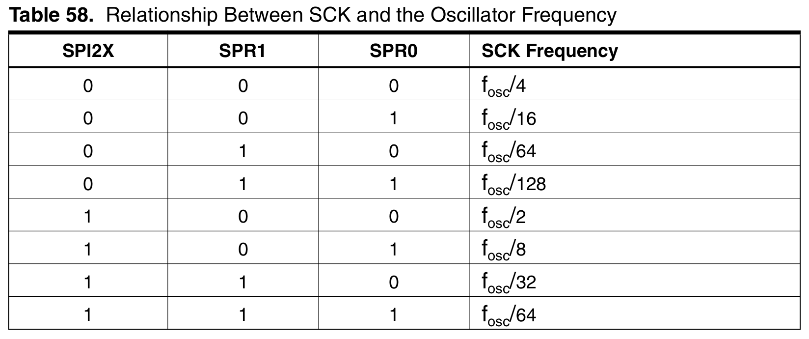
MHz. Below is a table with the available prescalers. See that the
smallest prescaler that will provide us with a frequency of less than
1.8 MHz is 16:
Remember that in addition to the SPI bus configuration, you must specify the direction (input / output) of the PB4 (output), PB5 (output), PB6 (input) and PB7 (output) pins.
Now let's move on to the SPI_MasterTransmit function, the data we want to send should be written to the SPDR register. To check whether the transmission has ended, the command is run:
while (! (SPSR & (1 << SPIF)));
The SPIF flag is 1 when the transmission is complete. So we check to see if the SPSR register is set to 1 on the SPIF bit. If so, the expression SPSR & (1 << SPIF) takes the value 1. Then it is negated and we get while(0), which causes the end of loop. So the program is no longer paused because the transmission has ended and we can go to other instructions.