Exercise 6: SPI bus
Activity 2
Goal:
MCP3202 is a 12-bit A/D converter that returns the voltage value using the SPI bus. In this exercise, we connect a potentiometer to the A/D converter and display the voltage value on the LCD display. Unfortunately, this exercise can only be done with a real hardware (no using simulIDE). If you do not have an ATmega32 board, I encourage you to watch the videos below to understand the general idea.
Connection:
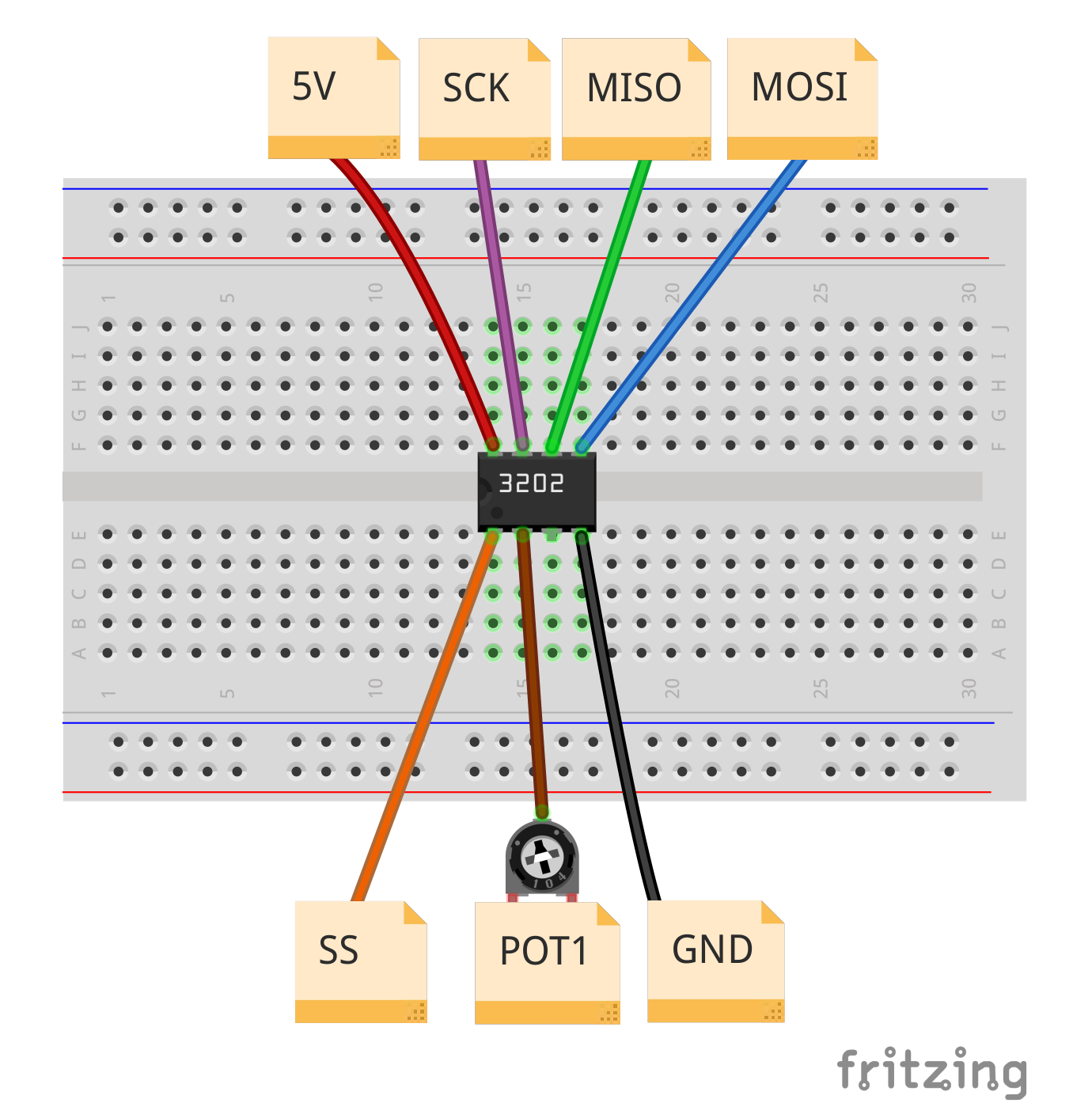
Let's start with the ways to connect the A/C converter:
Realization:
First, study the transmission protocol of the A/D converter. The following is an excerpt from the documentation for the MCP3202:
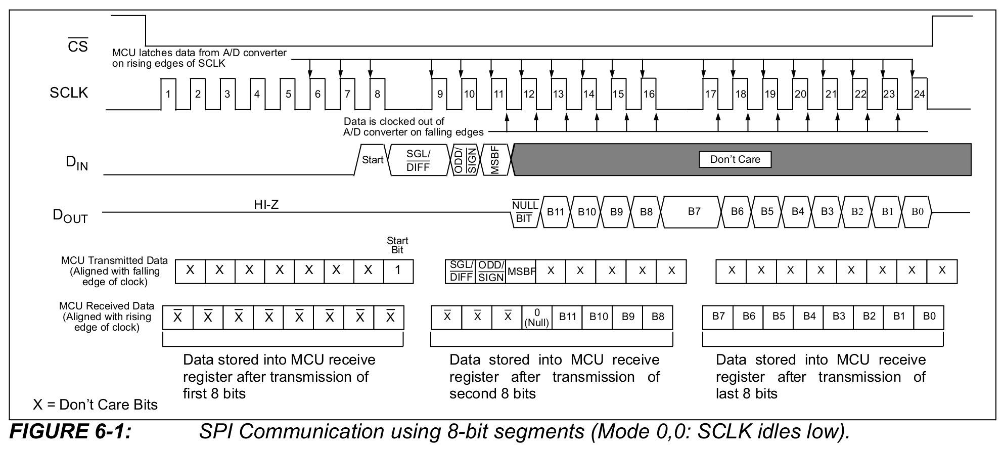
See that the transmission starts with a low state on the SS line (labeled here as CS). Then a byte is sent in the form:
xxxx xxx1
where 1 is the start bit.
Then the byte is sent in the form:
SGL ODD MSBF x xxxx
where SGL and ODD bits are responsible for the transmitter working mode and the channel selection. Take a look at the table below:
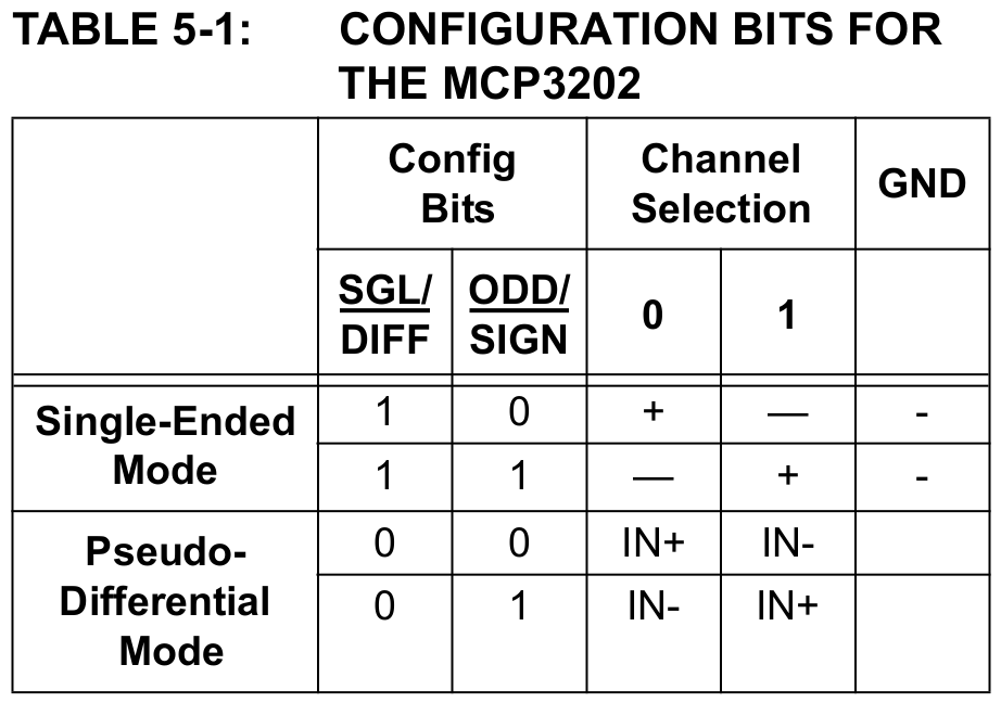
On the other hand, if we set 1 on the MSBF bit, the most significant bits will be sent first.
After sending this byte, the converter will return a byte where the 4 LSB bits are the 4 MSB bits of the value corresponding to the voltage measured by the converter.
Then send a byte consisting of any characters, e.g. all zeros. After that, the converter will send the 8 LSB bits corresponding to the measured voltage value.
You already know everything to do the activity yourself. Therefore:
1. Connect the MCP3202 converter chip to the microcontroller
2. Attach to the project the library for SPI bus, created in the previous pages.
3. Attach to the project the library of the LCD display, created in the previous exercises
4. Connect the LCD display to the microcontroller
5. Write the main program that will display on the LCD display the value read from the converter as a number and the measured voltage in volts [V] in the form of a floating point number (with 3 decimal places). Read the voltage from the converter with the Timer / Counter1 interrupt routine every 100ms.
When you are done, compare the result with the movie:
Extension: Enrich the program with determining the mean value from e.g. 10 measurements and displaying it under the measured actual value. You can prepare a procedure for determining a moving average (calculated at any time - cyclic buffer),
When you are done, compare the result with the movie: