Exercise 9: 1-wire bus
This activity is supplementary for those who have a hardware. Unfortunately, SimulIde software does not contain any elements communicating via the 1-wire bus, but we encourage you to watch at least the movie to understand the idea.
Main topic:
- 1-wire bus
1-wire bus
The 1-wire bus is not available in hardware form in the ATmega32 microcontroller, but the transmission protocol can be easily implemented. In this exercise, we will create a library to support the 1-wire bus based on the documentation (link). Unfortunately, simulIDE doesn't have any 1-wire device, so if you don't have a board, we encourage you to review the exercise anyway to understand the idea of using the 1-wire bus.
Step 1: Connecting:
Connect the DS18B20 temperature sensor output with the PB3 pin.
Step 2: Create a library for 1-wire support:
Below is a diagram of operations on the 1-wire bus and a table with recommended delays: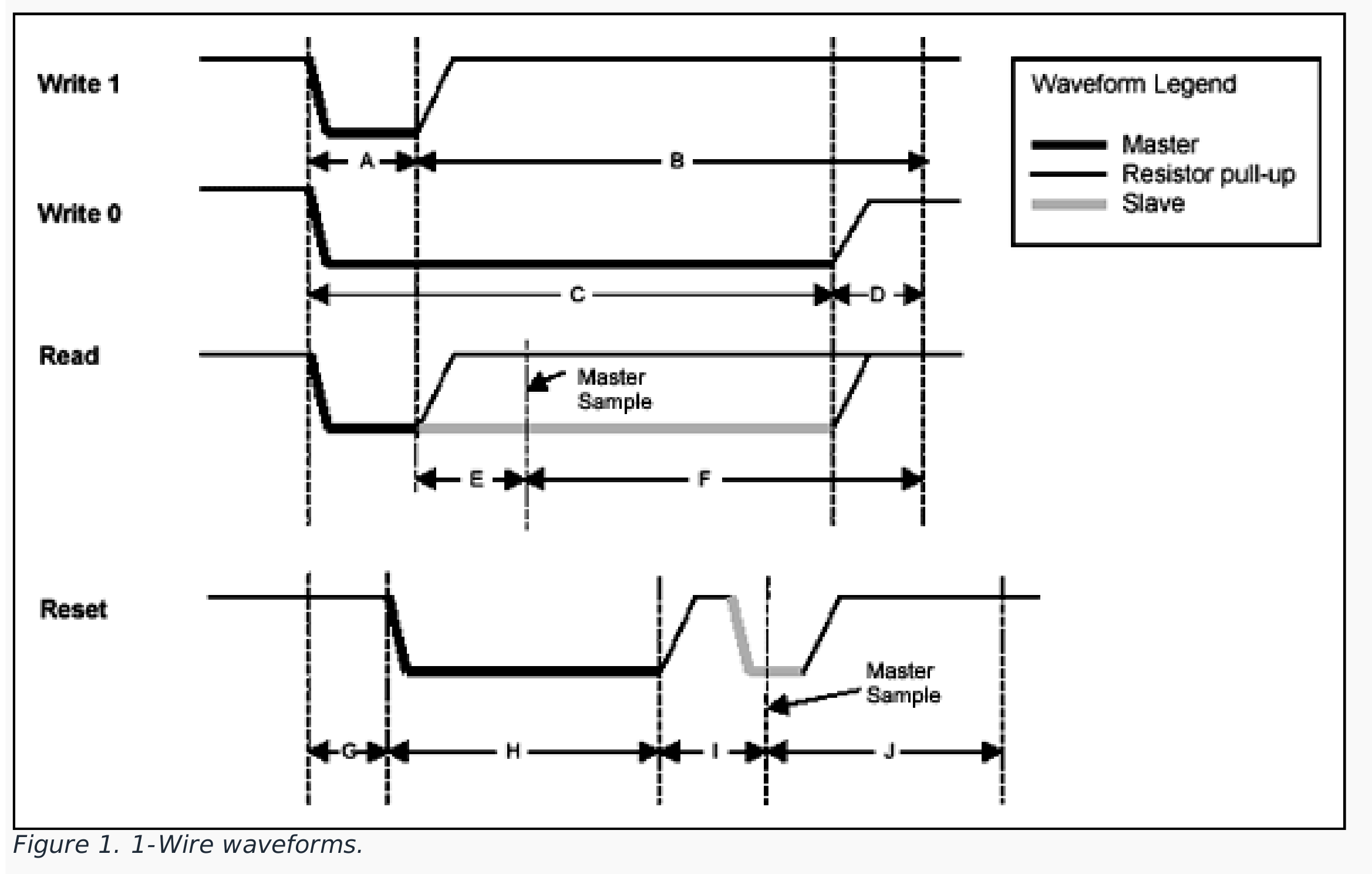
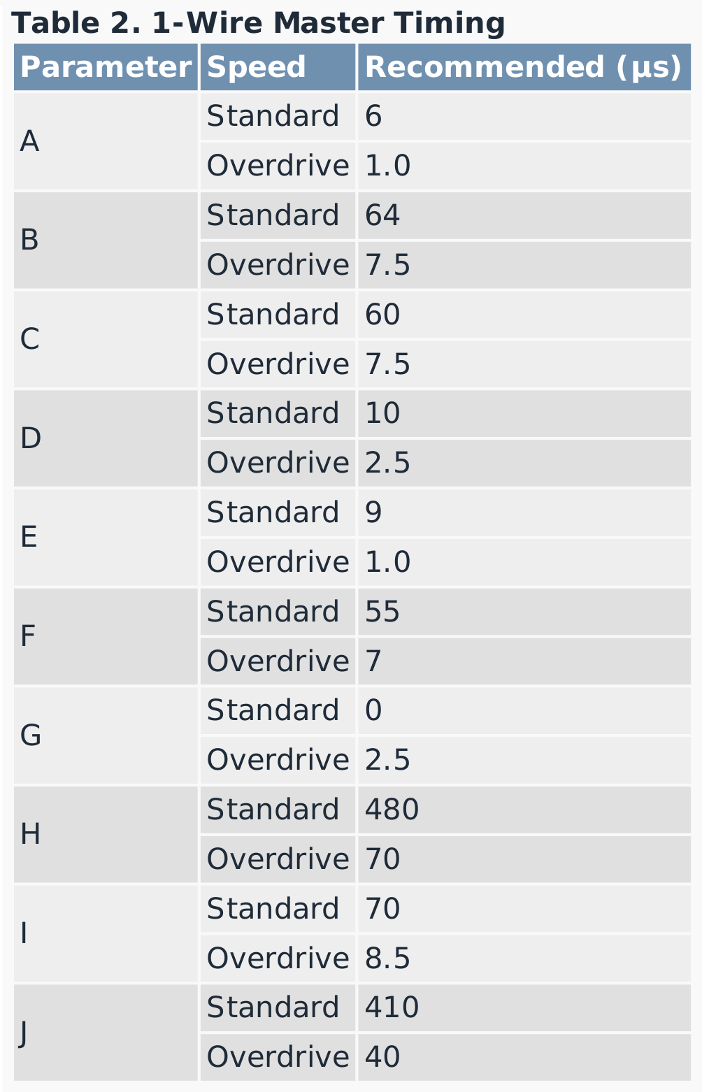
Based on the diagram above, let's create the following functions:
a) 1-wire reset function
According to the above diagram, in order to perform the reset:
1) Set the low state on the PB3 pin.
NOTE: The 1-Wire bus requires the use of a pull-up resistor pulling voltage to +5 V (high state on the bus). The low state will be when we change the direction of ATmega32 pin (PB3) to output and set the output value to 0. The high state on bus will be when we change the direction of ATmega32 pin (PB3) to input, and pull-up resistor will force the high state. This is convenient, because we can monitor the state of the bus in such case also.
2) Wait \( 480 \mu s \).
3) Set the high state on the PB3 pin.
4) Wait \( 70 \mu s \).
5) Read the value from the PB3 pin (presence pulse). If the read value is equal to 0, the device is connected to the bus. Otherwise, the device was not connected.
6) Wait \( 410 \mu s \).
7) Return presence pulse.
b) function sending data byte through the 1-wire bus:
The sending of the data byte will be performed bit by bit. Depending on the value of the bit, we will carry out the procedure to send the value 1 or 0.
To send the value 1 you should:
1) Set the low state on the PB3 pin.
2) Wait \( 6 \mu s \).
3) Set the high state on the PB3 pin.
4) Wait \( 64 \mu s \).
To send the value 0 you should:
1) Set the low state on the PB3 pin.
2) Wait \( 60 \mu s \).
3) Set the high state on the PB3 pin.
4) Wait \( 10 \mu s. \)
The greatest difficulty in implementing this function is how to send the value bit by bit. The easiest way is to make a for loop that runs 8 times and in the middle:
1) Check the value of the 1st bit, e.g. byte & 0x01. If this expression returns 1, the bit is 1.
2) Shift the bits to the right so that the next bits jump to the position of the 1st bit, for example: byte >> = 1;
c) function reading data byte:
Reading a data byte is also performed bit by bit. To read the bit:
1) Set the low state on the PB3 pin.
2) Wait \( 6 \mu s \).
3) Set the high state on the PB3 pin.
4) Wait \( 9 \mu s \).
5) Read the value from the PB3 pin.
6) Wait \( 55 \mu s. \)
Try to create your own 1-wire library based on the tips above. When you're finished, compare the result with the video: