Activity 2. RGB LED
This activity utilizes Arduino Uno output pins to
drive an RGB LED. The activity is divided into 2 parts: a) RGB LED vs LED, b)
RGB LED. (50 minutes)
Activity 2a
In this part the aim is to operate an RGB LED and compare it to a simple LED. More specifically, the RGB LED changes color between the three primary colors every second, while the simple LED lights up permanently.
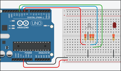
Step 1. Draw the next circuit in Tinkercad and complete the LED connection so that its anode goes to pin 12 of the Arduino Uno
Step 2. Study the code and write it on the microcontroller:
 /* RGB LED vs LED
 Circuit
 Connections:
 PIN_12 => LED_Anode - LED_Cathode =>  Resistor 220Ω => Gnd
 PIN_9  => Resistor 220Ω           =>  Red pin of RGB LED
 PIN_11 => Resistor 220Ω           =>  Blue pin of RGB LED
 PIN_10 => Resistor 220Ω           =>  Green pin of RGB LED
*/
#define R_pin 9        //give the name “R_pin” to PIN_9
#define G_pin 11          //give the name “G_pin” to PIN_11
#define B_pin 10          //give the name “B_pin” to PIN_10
#define LED_pin 12        //give
the name “LED_pin” to PIN_12
//The setup() function initializes and sets the initial values
//It will only run once after each powerup or reset
void setup()
{
  //Configures the PIN_9, PIN_10, PIN_11 and PIN_12 to behave as outputs
  pinMode(R_pin, OUTPUT);
  pinMode(G_pin, OUTPUT);
  pinMode(B_pin, OUTPUT);
  pinMode(LED_pin, OUTPUT);
}
 //This function loops consecutively
void loop()
{
 digitalWrite(LED_pin, HIGH); //Write a HIGH value (5V) to digital pin 12 – LED on
 //red color for RGB = > R=255, G=0, B=0
 analogWrite(R_pin, 255); //Write 100% PWM to pin9
 analogWrite(G_pin, 0);     //Write 0% PWM to pin 11
 analogWrite(B_pin, 0);     //Write 0% PWM to pin 10
 delay(1000);               // Wait for 1 second
 //green color for RGB = > R=0, G=255, B=0
 analogWrite(R_pin, 0);     //Write 0% PWM to pin 9
 analogWrite(G_pin, 255);   //Write 100% PWM to pin 11
 analogWrite(B_pin, 0);     //Write 0% PWM to pin 10
 delay(1000);               // Wait for 1 second
 //blue color = > RGB=0,0,255
 analogWrite(R_pin, 0);     //Write 0% PWM to pin 9
 analogWrite(G_pin, 0);     //Write 0% PWM to pin 11
 analogWrite(B_pin, 255);   //Write 100% PWM to pin 10
 delay(1000);               // Wait for 1 second
}
Step 3. Run the simulation and check the correct operation of the circuit