Activity 1. Serial and LEDs
This activity uses serial communication between the PIC18F4550 and a serial monitor. 8 LEDs are connected to the PORTD.
(50 minutes)
Activity 1a
The PIC18F4550 reads the serial port and activates the appropriate LED. The commands are:
- 0’ => all LEDs turned OFF
- ‘1’ => 1st LED turned ON
- ‘2’ => 2nd LED turned ON
- ‘3’ => 3rd LED turned ON
- ‘4’ => 4th LED turned ON
- ‘5’ => 5th LED turned ON
- ‘6’ => 6th LED turned ON
- ‘7’ => 7th LED turned ON
- ‘8’ => 8th LED turned ON
- ‘9’ => all LEDs turned ON
- Anything else is considered a wrong command
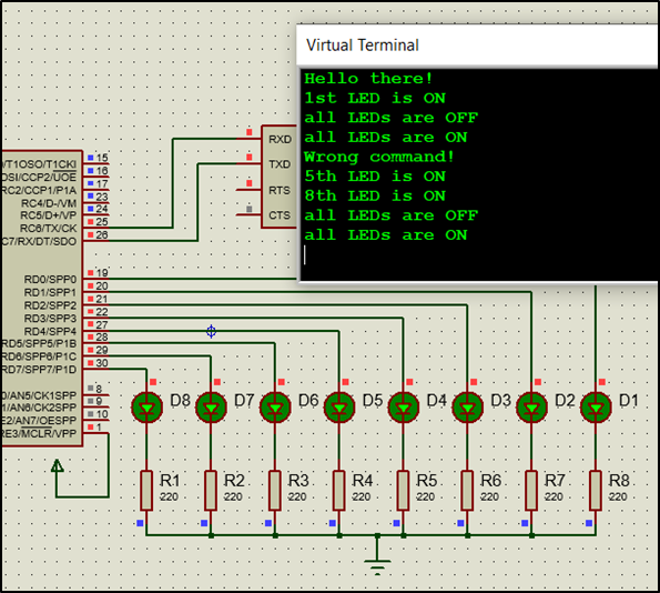
Step 1. The circuit is drawn in the Proteus Design Suite.
Step 2. The program in C language is written.
Write in CCS C Compiler the program in C language
#include <main.h> // the file main.h with the
// initial settings is included.
// This file must be placed in the same
// folder with the project.
// Also the 18F4550.h file must exist
// in the same folder with the project
#byte PORTD =0xF83
// We attribute to the memory position 0xF83 the name PORTD.
// This means that we define a 8 bit variable whose value
// will be stored to the memory position F83h.
// The memory position F83h is the PORTD data register.
#byte PORTC=0xF82 // F82h is the position or PORTC data register
// at the data memory of the microcontroller
// SFR Special Function Register
//This directive tells the compiler the baud rate and pins used for serial I/O
//baud rate=9600, parity=no, TX=RC6, RX=RC7, bits=8, stop bit=1
#use rs232(uart1,baud=9600,PARITY=N,XMIT=PIN_C6,RCV=PIN_C7,bits=8,STOP=1)
//variable to hold incoming data from serial communication
char serialData;
// ********* main program ************************
void main() {
set_tris_d(0x00); // PORTD is defined as output
set_tris_c(0b10000000); // RC7=input, RC6=output
PORTD=0xFF; // all LEDs turn OFF
printf("Hello there!\n\r"); // sends a string of characters over RS232 transmission pin (TX)
//By sending \n\r to serial communication
//the cursor is moved to the beginning of the next line
//so that there is a better display on the monitor.
while(TRUE){
if(kbhit()){ //test if a character is ready for getc() function
serialData = getc(); //read the character
//command identification
if(serialData == '0'){
PORTD=0; // all LEDs are OFF
printf("all LEDs are OFF\n\r");
}
else if(serialData == '1'){
PORTD=0b00000001; //1st LED is ON
printf("1st LED is ON\n\r");
}
else if(serialData == '2'){
PORTD=0b00000010; //2nd LED is ON
printf("2nd LED is ON\n\r");
}
else if(serialData == '3'){
PORTD=0b00000100; //3rd LED is ON
printf("3rd LED is ON\n\r");
}
else if(serialData == '4'){
PORTD=0b00001000; //4th LED is ON
printf("4th LED is ON\n\r");
}
else if(serialData == '5'){
PORTD=0b00010000; //5th LED is ON
printf("5th LED is ON\n\r");
}
else if(serialData == '6'){
PORTD=0b00100000; //6th LED is ON
printf("6th LED is ON\n\r");
}
else if(serialData == '7'){
PORTD=0b01000000; //7th LED is ON
printf("7th LED is ON\n\r");
}
else if(serialData == '8'){
PORTD=0b10000000; //8th LED is ON
printf("8th LED is ON\n\r");
}
else if(serialData == '9'){
PORTD=0xFF; //all LEDs are ON
printf("all LEDs are ON\n\r");
}
else{
printf("Wrong command!\n\r");
}
}
}
Step 3. Compile the program in C in order to create the program in the microcontroller machine code (hex file).
Step 4. Load to the microcontroller the hex file (program in machine code) that was created from the CCS C Compiler.