Introduction to electronics
Here is its content:
1. Models vs reality
2. Sources - types and characteristics
3. Main electronic components
4. Measurements and instruments
5. Connections
Main electronic components
A capacitor with a capacity C does not conduct direct current and in the ideal case constitutes an opening in the circuit for such a current, while for a sinusoidal alternating current of frequency f it has an impedance of \( \frac{1}{j\omega C} \), where \( \omega = 2 \pi f \). The voltage on the capacitor also changes when a larger charge reaches it, i.e. during charging, but also during discharge (current flows through it in both cases) \( i = C (\frac{du}{dt}) \).
A coil with inductance L conducts a direct current and is ideally a short circuit in the circuit of such a current, while for a sinusoidal alternating current with a frequency f it has an impedance \( j \omega L \). When the intensity of the current flowing through the coil changes, the voltage \( u_{L} = L (\frac{di}{dt}) \) is created on the coil due to the self-induction phenomenon.
The working parameters of the passive elements are:
permissible operating voltage Umax for the capacitor,
permissible current intensity Imax for the coil,
for resistors the permissible power of losses Pmax.
For worldwide produced resistors, their nominal resistance is given in ohms, kilohms or megohms. Nominal values belong to one of several tolerance resistance groups. This is due to the fact that the resistors coming out of the production lines have values different from the nominal values (statistical distributions) and this must be remembered when using a resistor in a specific case, because the manufacturer guarantees that the selected resistor will have a resistance different from the nominal one, but within a known range.
Nominal values for R were obtained from a requirement for one decade that with an acceptable tolerance of resistance, e.g. 5% ( 0.95R <R <1.05R), the entire range of values should be covered within one decade. Values for the remaining decades are covered by multiplying or dividing by a multiple of 10. The commonly accepted values around the world correspond to the tolerances of 20%, 10%, 5%, 2%, 1%, 0.5%, 02%, 0.1%, and the series of values are marked as E3, E6, E12, E24, E48. E96, E192 respectively. The main values for the tolerances encountered in practice are presented in Table:

It should be noted that for values from the main series, i.e. E6, E12, E24, two-digit values are given, while for values from the precise series E48 (2%), E96 (1%), E192 (0.5%) three-digit values are given. For high-load resistors and for the main series, the nominal values are given directly, with the rule of three characters being adopted: two characters are value digits, and the third one is the k (kilo) or M (mega) suffix, which also serves as a decimal point. This rule applies to mass resistors with resistances in one of the six decades from 10 \( \Omega \) to 10 \(M \Omega \), e.g. 2M7 is 2.7 MW, M27 is 0.27 \(M \Omega \) = 270 \(k \Omega \), 27k is 27 \(k \Omega \), 2k7 is 2.7 \(k \Omega \), k27 is 270 \( \Omega \), and 27R is 27 \( \Omega \).
It is worth noting that the idea of value determination presented above applies fully to resistors, but has also been partially applied to capacitors and coils.
The load capacity of resistors, expressed in watts, is directly related to their size:
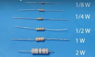
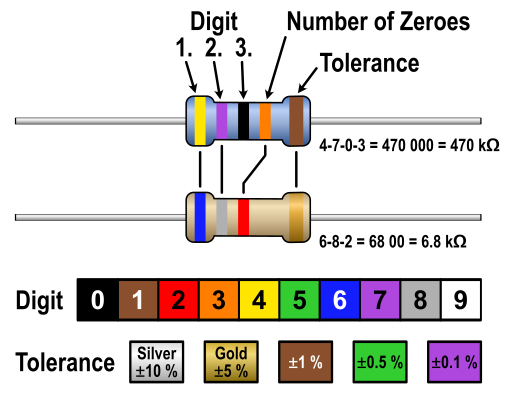
Its determination is based on the fact that with the increase of the power lost in the resistor, its temperature increases, which in turn increases its resistance. Therefore, the load capacity of a resistor is understood to mean the power at which an increase in the temperature of the resistor causes the resistance to increase beyond the range resulting from its tolerance. Resistors for traditional assembly, i.e. through-hole assembly, have a load capacity of 2W, 1W, 0.5W, 0.25W, 0.125W, and while the resistors with the highest resistances can be marked with the above-mentioned rule, the resistors with the lowest resistances use the markings in the form of colored stripes according to the bar code presented in: