Introduction to electronics
Here is its content:
1. Models vs reality
2. Sources - types and characteristics
3. Main electronic components
4. Measurements and instruments
5. Connections
Measurements and instruments
Analysis of the influence of measuring instruments on the operation of the circuit
Influence of the voltmeter on the voltage at the load
Assumptions: the analog voltmeter has a characteristic resistance
of 10 \( k\Omega/V \) and it is set to the range of 1 V, hence it then has
a resistance RV = 10 \( k\Omega \).
Circuit without instruments (actual voltages) :
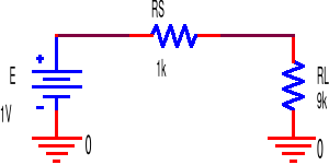
\( U_{L} = E \frac{R_{L}}{R_{S}+R_{L}} = 1 V \frac{9 k\Omega}{1k\Omega + 9k\Omega} = 0.9 V \)
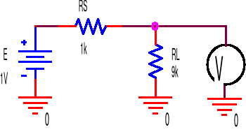
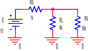
Absolute error of voltage measurement on the load: \( \Delta U_L = U'_L - U_L = 0.826V - 0.900 V = -0.074 V \)
Relative error of voltage measurement on the load: \( \delta U_L = \frac{\Delta U_L}{U_L} = \frac{-0.074 V}{0.900 V} = -0.083 = -8.3 \)%
Where did the assumptions come from?
Analog voltmeters (electric, passive) are built as a series connection of a magnetoelectric meter and precise resistor (series resistor) with resistance depending on the set measuring sub-range. Such voltmeters are characterized by the characteristic resistance expressed in \( k \Omega / V \) (here the value of 10 \( k \Omega / V \) was adopted). It was also assumed that the multi-range voltmeter has the sub-ranges of 0.3V, 1V, 3V, 10V, 30V, 100V, 300V. Due to the obvious requirement of obtaining the highest possible accuracy, the range of 1.0V was selected, as according to Fig. 4.1.1, the voltage on the load is 0.9 V (in laboratory practice, the approximate value will be obtained from preliminary measurements!). Thus, the resistance of the voltmeter in this range is: RV = 10 \( k \Omega / V \) * 1 V = 10 \( k \Omega \), Note: Digital voltmeters have an input resistance (internal) independent of the range and typically equal to 10 \( M \Omega \).
2. Influence of the ammeter on the current in the load
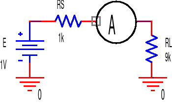
Assumption: the ammeter has an internal resistance RA = 2 \( k\Omega \).
Circuit without instruments (actual currents):
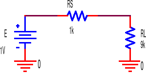
\( I = \frac{E}{R_S + R_L} = \frac{1 V}{1 k\Omega + 9k\Omega} = 0.1 mA = 100 \mu A \)
Circuit with instruments (currents in this state):
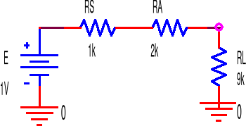
\( I' = \frac{E}{R_S + R_L + R_A} = \frac{1 V}{1 k\Omega + 9 k\Omega + 2 k\Omega} = 83.3 \mu A \)
Where did the assumptions come from?
The ammeters are built as a combination of a magnetoelectric meter and shunt resistor (parallel resistor) with a resistance depending on the set measuring range. In the commonly used Ayrton shunt system, multi-range ammeters have the property that their shunt resistances are selected in such a way that the voltage across the ammeter is always the same at different ranges (often 0.2V); hence the resistance of the ammeter in the different ranges can be easily calculated. In the given example, assuming that the ammeter works in the sub-range 100 uA, its resistance is therefore RA = 200 mV / 100 \( \mu A \) = 2 \( k \Omega \). This principle also applies to digital ammeters.
Absolute error of the load current measurement: \( \Delta I = I' - I = 83.3 \mu A - 100 \mu A \)
Relative error of load current measurement: \( \delta I = \frac{\Delta I}{I} = \frac{-16.7 \mu A}{100 \mu A} = 0.167 = -16.7 \)%
After analyzing the influence of the measuring instruments on the operation of the circuit, the accuracy of the measurements should be assessed using the metric of the instrument used, provided by the manufacturer. It is different for analog devices than for digital devices.
The accuracy of measurements with analogue instruments is determined on the basis of the specified instrument class k, defined as the ratio of the absolute error Dx expressed as a percentage to the value corresponding to the maximum pointer deflection xmax. Knowing the meter class k [%] and xmax, first the absolute error (constant for a given range) is calculated Dx = xmax * 0.01* k, and then having the absolute error \( \Delta x \) and the indicated measured value x, the relative measurement error \( \delta x = \frac{\Delta x}{x} \) is determined.
The accuracy of measurements with digital instruments is determined as follows: The accuracy for the range used, given in percent, should be multiplied by the read voltage or read current value and the value indicated in the manual shall be added corresponding to the change in the last digits of the indicator (usually by one, two or more, usually marked as digit value).
Another characteristic parameter of a measuring instrument is its resolution, defined as the smallest change recorded by the instrument. In the case of analog devices, the resolution is usually the value of the measured quantity that corresponds to the change of the pointer position by half of the smallest division. In the case of digital instruments, the measurement resolution means a change in the value of the measured quantity by 1 of the least significant digit, e.g. for a 3.5-digit meter in the 2 V range, the highest indication is 1.999 V, and the resolution is 0.001 V. accuracy and resolution in the case of digital instruments (wrongly stating that the accuracy of measurements with a meter 3.5 digit with a nominal range of 2.000 V is 0.001 V - = 1 mV).
Comparison of the properties of various multimeters (multimeters) as an example DC voltmeters
Properties |
Electric meter UM-112B type by ERA |
Electric meter V-640 type by ELPO |
Digital meter type M-3610 by METEX |
Reset |
Manual mechanical |
Manual mechanical and electric |
Automatic electric |
Need for power supply |
No |
Yes |
Yes |
The position of the meter during operation |
horizontal |
horizontal |
any |
Change of polarity |
manual |
manual |
automatic |
RWE on various range |
variable: |
constant: 100 M\Omega |
constant: 10 M\Omega |
Input |
"Floating" |
“Single-ended” [correct ground connection necessary] |
"Floating" |
Accuracy |
class 1 + reading error |
Class 1.5% (± 1.5% of the span value) |
±0,3% rdg + 1 dgt |
Resolution |
0.5 div |
0.5 div |
1/2000 range (3½ digital instrument) |
Voltage drop with current measurement |
30..480 mV depending on the scope |
5 or 50 mV depending on the sub-range |
200mV |
Notes on the M-3610:
rdg (reading) - measured value (!),
dgt (digit) - voltage value corresponding to the change of the last digit on the display by one