Introduction to electronics
Here is its content:
1. Models vs reality
2. Sources - types and characteristics
3. Main electronic components
4. Measurements and instruments
5. Connections
Connections
The simplest connections of elements into circuits in school laboratories, during the demonstration of their operation, are usually made with the use of copper wires in the form of a cord, terminated with banana plugs (connectors colloquially called "bananas") or, less frequently, with fork plugs (in the case of currents greater than a few amperes). Radio sockets (banana sockets) or laboratory terminals work with banana connectors (plugs).
In the case of many modern electronic systems made in the form of printed circuits, there is sometimes a need to modify the connections. Then, miniature cables with female ends, also miniature ones, are used, which cooperate with pins soldered into the boards (sometimes called goldpins). Similar miniature cables, but with male ends, are used when connecting circuits on universal boards containing entire socket fields (sometimes called “breadboards”).
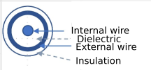
Particular connections are used when transmitting signals to and from measuring instruments. Coaxial cables are used for this purpose. They are two-wire transmission lines with such a geometry that the electric and magnetic fields are contained within a limited area. These lines form two concentric conductors, the cross-sectional view of which is shown in Figure:
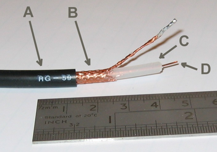
Source: 
Flexible coaxial cable composed of:
- Outer plastic sheath
- Woven copper shield
- Inner dielectric insulator
- Copper core
The inner copper conductor is surrounded by a polyethylene insulating sheath, and on it is the outer conductor coated with a layer of external insulation. The cables are made of copper, not solid, but in the form of a cord (internal conductor) or mesh (braid), so that the coaxial cable is not stiff but flexible. The advantage of this type of geometry is that the electric and magnetic fields from the currents flowing through the inner and outer conductors are contained only inside and not outside the cable and therefore do not interfere with other nearby electrical circuits. At the same time, the influence of external electromagnetic fields is greatly reduced. The main parameter of a coaxial cable is its characteristic resistance, most often 50 Ohm in electronic measuring technology.
The cooperation of coaxial cables with measuring instruments, such as generators or oscilloscopes, requires the use of appropriate connectors. The devices have sockets and the coaxial cables are fitted with plugs. British Naval Connector (BNC) connectors have become widespread in electronic measurement technology. These are bayonet connectors: the socket contains two small pins (bayonets) located at the two ends of the diameter, and the plug on the cable has a movable clamp with notches overlapping the bayonets in the socket and allowing to hook the movable part of the plug on the cable against them and thus prevent accidental disconnection of the plug from the socket. Sometimes it is necessary to connect a coaxial cable to the tested system without a BNC type socket, but with radio (banana) sockets, one of which is connected to the ground. Then you need to use a coaxial cable with two bananas connected on one side: one (usually red) is connected to the inner conductor of the cable (usually also with a short red wire) and the other, usually black, is connected to the braid. The first end is called "hot", the other end is "cold". The rule is to connect the cable to the tested system first with the "cold" terminal (cold end connector with ground), and only then with the "hot" terminal; when disconnecting, the order is reversed: the "hot" end of the cable is disconnected first, and the cold end is disconnected at the end.
In an electronic system, the term mass (ground - GND) is understood as a node in the system to which the greatest number of branches is connected. The ground potential is the reference against which the voltages are determined and measured. It should be stated here that grounding is not generally the same as an Earth connection. For safety reasons, the housings of measuring instruments powered from the 230V / 50Hz mains are earthed for safety reasons, while the battery-powered devices are not necessarily. Thus, not always the ground is connected to the earth clamp.
At the end of the section on connections, the four-terminal method of connecting the load to the source will be presented. This is frequently used for precise measurements of impedance of components (like resistance, where current has to be supplied and voltage drop has to be measured). The need to use this method results from the need to reduce in many cases the influence of cables connecting the source with the load. We will present its principle on the example of resistance measurement at a load distant from the source (Fig. 5.2). If the voltmeter was connected to the measuring circuit close to the source, and it is necessary to know the voltage on the load, the measurement result would be burdened with a systematic error resulting from the resistance of the wires connecting the source with the remote load, because the indicated voltage would be greater by the voltage drop on the wires caused by the flowing current. Therefore, an additional pair of wires is added, supplying the measured voltage directly to the voltmeter. This improves the measurement, as a negligible current flows through the additionally connected cables, due to the fact that the resistance of the voltmeter is high. The method presented here has many different applications, both in DC circuits (microprocessor-based measurement of physical quantities with a resistance sensor, Fig. 5.3) and in variable current circuits, e.g. when measuring electronic components with an impedance meter for RLC parameters in the high frequency range.
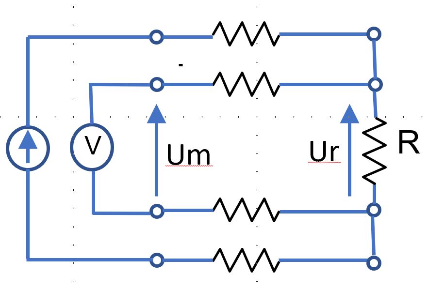
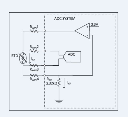
Fig 5.3. Measurements with resistance sensor using specialized integrated circuit.