Basic electronic instruments - theoretical introduction
- properties and parameters of power devices,
- rules of using power supplies and basic measuring devices (analog and digital universal meters)
Power devices
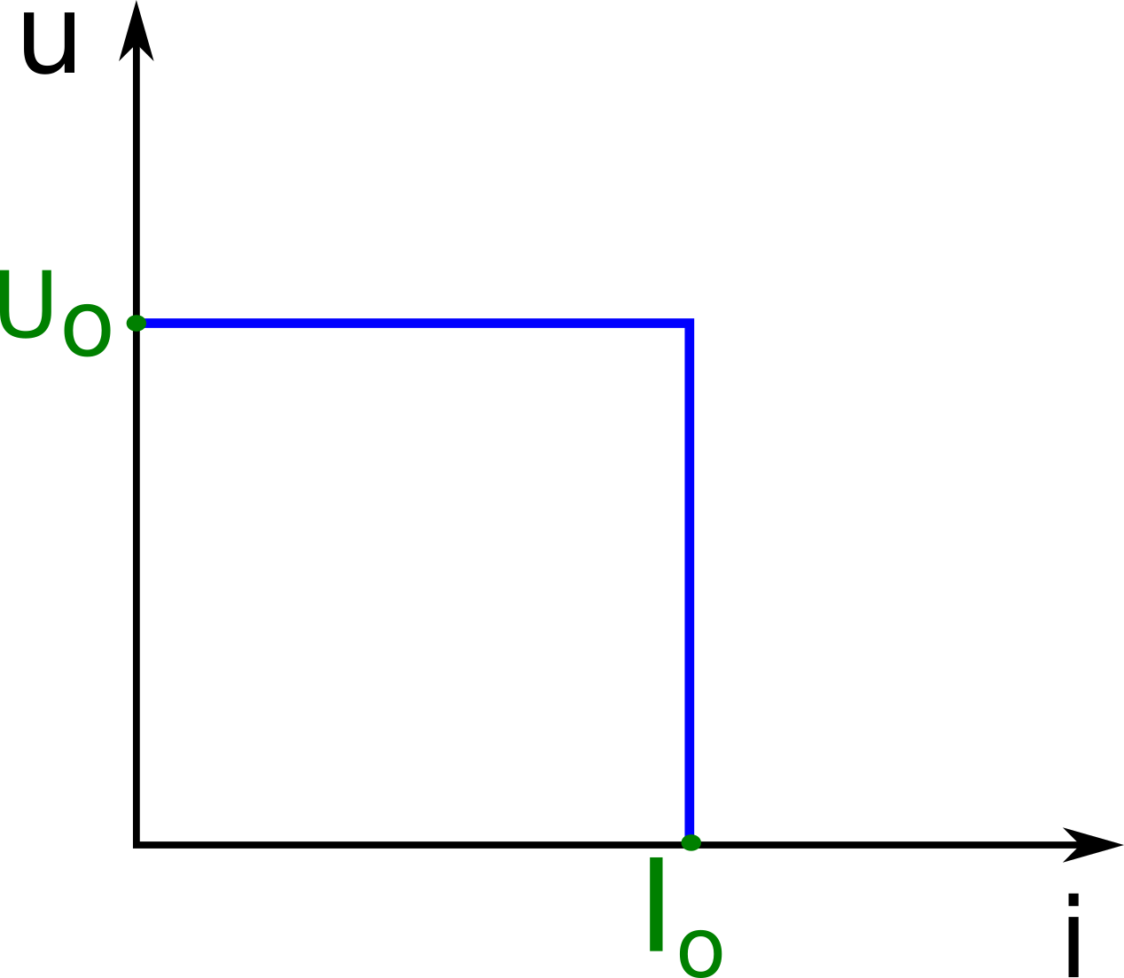
Electronic devices require electricity, which usually comes from direct voltage sources (very rarely from direct current sources). An ideal DC voltage source has zero internal resistance so it will always provide a constant output voltage regardless of the load. In practice, the power supply devices should have a constant voltage only in a finite range of the load current. Why? Suppose you connect an electronic device with a short circuit to a power device. A perfect short circuit is characterized by zero resistance between the terminals (in practice, the resistance is close to zero). According to Ohm's law (I = U / R), with zero resistance, the short-circuit current would be infinitely large, and in the case of real sources - unacceptably high. In the event of a short circuit, the supply devices should have a voltage of 0 V at the terminals. Hence, power devices should only expose a constant voltage up to a predetermined maximum load current. In summary, the following output characteristics of the power device (output - because it gives the relationship between voltage and current for the output terminals of the device) are desirable:
\( u = U_o \: for \: i< I_o \)
\( i = I_o \: for \: u<U_o \)
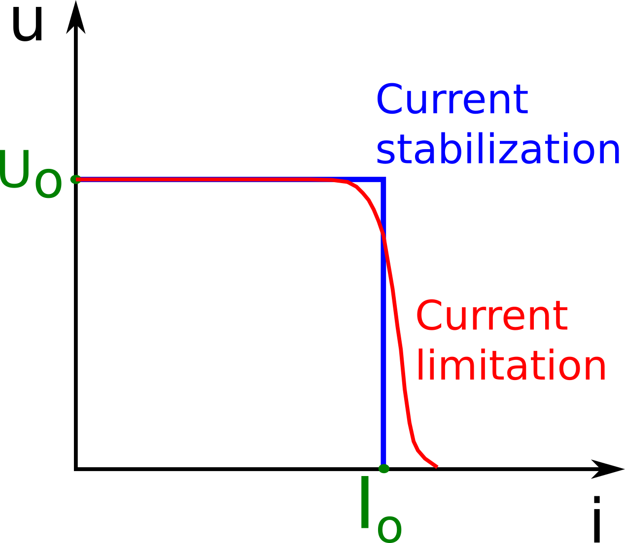
which means that the output voltage is constant and equal to \(U_0\) at load currents not exceeding \(I_0\), and at load current \(i = I_0\), the output voltage u drops sharply from \(U_0\) to zero (the power supply behaves like an ideal current source).
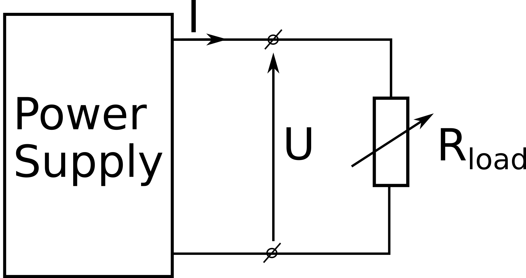
For practical reasons, it is desirable to be able to adjust both the voltage and the current.
On the other hand, with already set values of \(U_0\) and \(I_0\), the operating conditions of the power supply depend only on the resistance \(R\) of the system loading the power supply. The geometric structure presented in the figure below facilitates the analysis of the power supply operation. A load with resistance \(R\) represents a straight line through the origin of the \(u\), \(i\), inclined at an angle \(\alpha\) such that \(R \sim tg \alpha\).
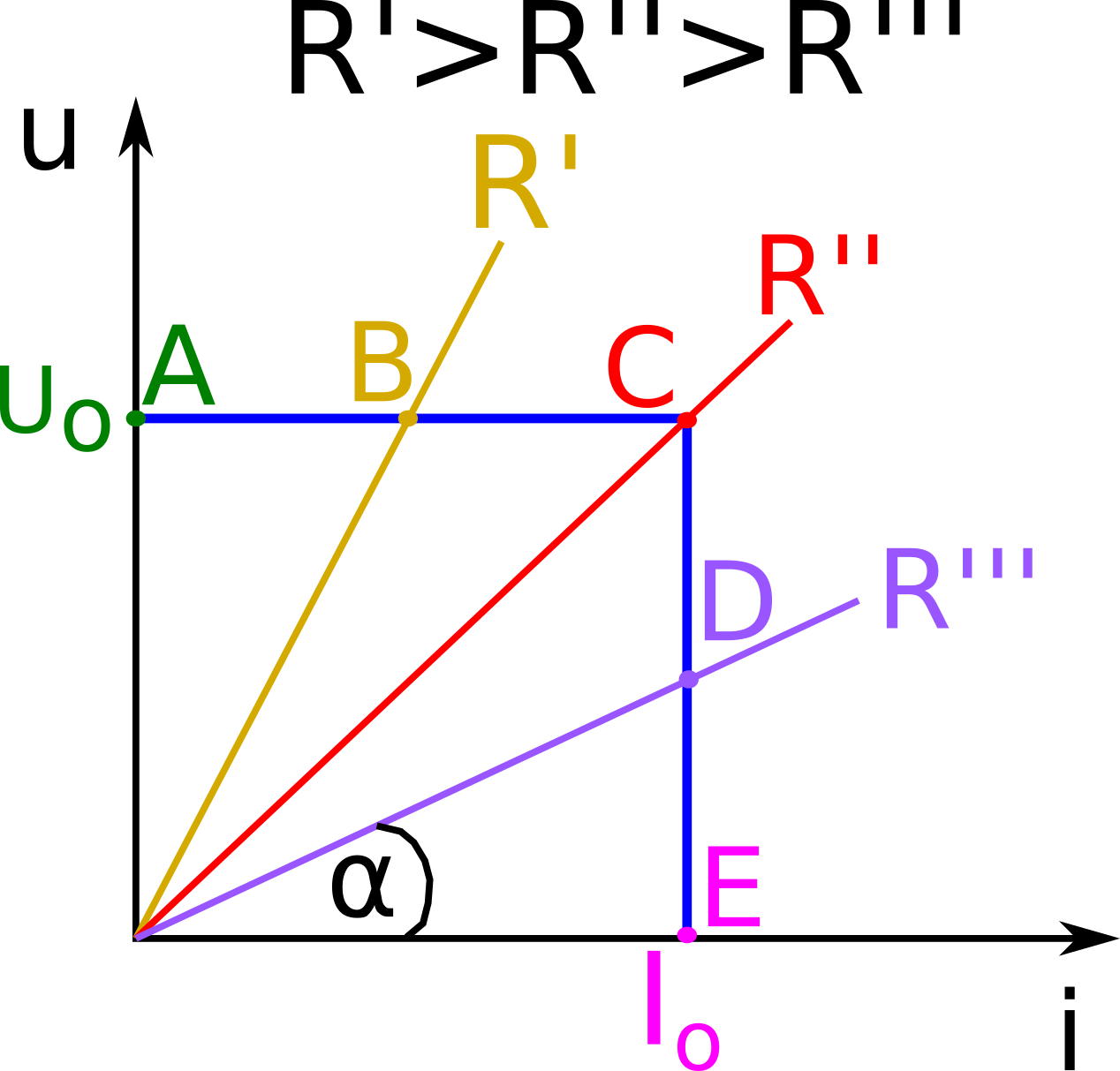
When the power source is unloaded, its output voltage is \(U_0\) (point \(A\) in the figure) and is maintained at this value while reducing the resistance \(R\) to the value \(R ''\) at point \(C\) (the source supplies different currents at different values of \(R\)). At point \(C\), corresponding to the characteristic \(R'\)' value, the current intensity is \(I_0\). With a further reduction of the resistance \(R\) below the value of \(R'\)', the output current is always the same, while the output voltage decreases and when the terminals of the power supply device (point \(E\)) are shorted, it reaches zero volts.
The actual power supply devices exhibit similar properties, except that on the output characteristic, the sections corresponding to the horizontal and vertical sections of the ideal power supply characteristic now have a certain slope. This is because they represent not ideal but real voltage and current sources.
A power supply device that draws energy from an AC network is called an AC adapter. In its simplest form, the power supply comprises a mains transformer that supplies an alternating voltage (usually reduced) to a semiconductor diode rectifier to which a ripple smoothing filter (capacitor \(C\)) is connected.
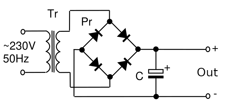
Such an unstabilized power supply has an output characteristic that significantly deviates from the characteristics of an ideal voltage source, and therefore a voltage stabilizer is often attached to it:

The stabilized power supply system is completed with blocks that limit or stabilize the output current, the essence of which is illustrated by the output characteristics shown in the figure below:
The basic parameters of stabilized power supplies are:
1.the range of voltage and output currents,
2.internal resistances during voltage and current stabilization,
3. the constancy of the output voltage and current with changes in the mains voltage, variously determined by
different manufacturers (which should be considered when comparing), e.g. as a ratio relative changes in the network voltage to the corresponding relative changes in voltage (current) the output voltage or its reciprocal, or as a relative change in the output voltage (current) at mains voltage changes within the given limits or by a known percentage,
4. constancy of voltage and output current with changes in ambient temperature.