Basic electronic instruments - theoretical introduction
- properties and parameters of power devices,
- rules of using power supplies and basic measuring devices (analog and digital universal meters)
Analog and digital universal meters
Universal meters (multimeters) are used to measure voltages and currents, both direct and alternating. Depending on the model of the meter, they can also be used to measure resistance, capacity, temperature and system continuity. The selection of the measured quantity is made with a switch. Another switch is for range selection, although some models have only one switch for range selection and the measured value. Some meters have automatic range selection for the measured quantity. As an indicator, a magnetoelectric meter is used - in analog multimeters, or a digital indicator - in digital multimeters. The magnetoelectric meter will be discussed in more detail below.
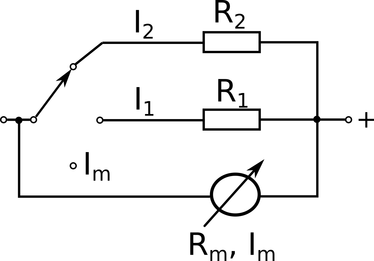
A magnetoelectric meter is, in principle, a sensitive ammeter with a constant current \(c_i\) (expressed e.g. in microamperes per division), resistance \(R_m\) and \(I_m\) range, also known as the nominal current of the meter, which in multimeters is usually from 10 \(\mu A\) to about 500 \( \mu A \).
By attaching shunts to the meter (parallel resistors of the appropriate value - see the drawing), the range of measured current intensities is extended to approximately 1 A or 10 A.
In the other position of the mode selector, series resistors (see figure below), are connected to the magnetoelectric meter, enabling the microammeter to be transformed into a voltmeter with various voltage measurement ranges (usually from about 0.1 V to about 1000 V).
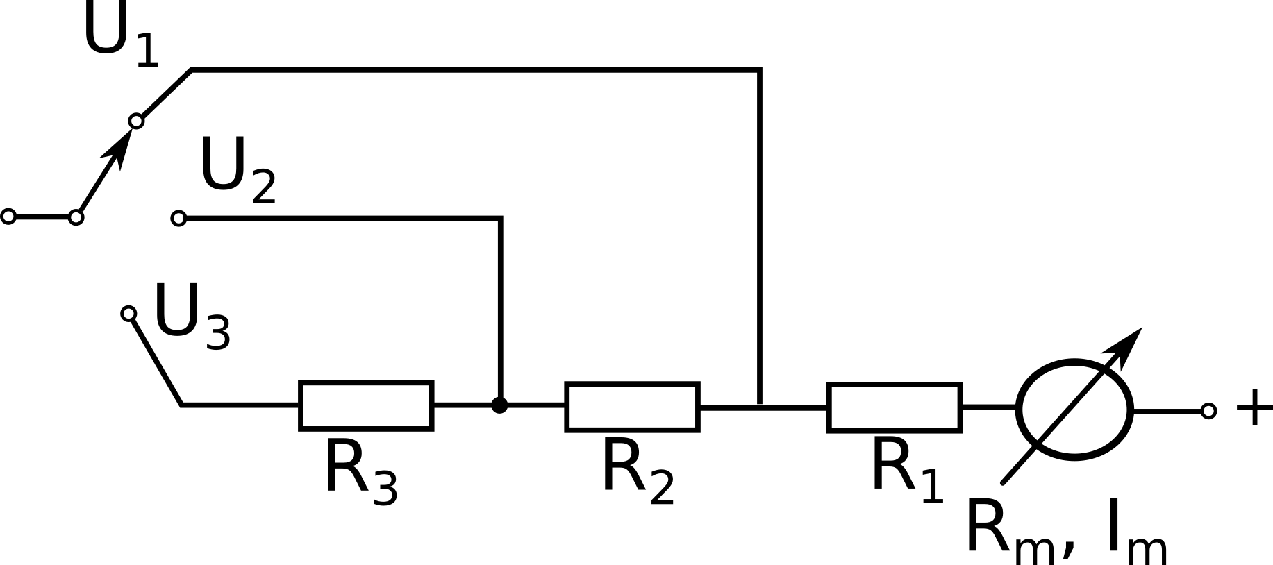
The basic parameters of the analog multimeter (apart from the ranges of measured voltages and currents) are: input resistance and the accuracy class of the device.
The input resistance of the voltmeter \(R_v\) is determined by the nominal current of the magnetoelectric meter used, \(I_m\), and is given as the number of kilohms per 1 V of any measurement voltage range.
A multimeter operating as an ammeter is characterized by the voltage drop across the ammeter (usually nearly range independent).
The concept of the accuracy class is more complex and will be explained separately.
By attaching a rectifier, it is possible to measure alternating voltages and currents with a multimeter. The device is then characterized by a different value of the input resistance, usually smaller, even by an order of magnitude, and the accuracy class, usually worse. When measuring alternating voltages and currents, attention should be paid to the limitation of the frequency range of the measured voltages and currents, and the related increase in the measurement error. The meter of alternating voltages and currents reacts to the average value of the measured quantity after rectification, and it is measured in the effective values of the sinusoidal quantities varying in time. Therefore, when measuring voltages and currents of non-sinusoidal variables, one should take into account the systematic error of indications, caused by the fact that the shape factor of the measured waveform is different from the shape factor for a sinusoid equal to \(k = \frac{\pi} {2 \sqrt {2}} = 1.1107\) (the shape factor \(k\) is defined as the ratio of the effective value \(U_{ev} = \sqrt{\frac{1} {T} \int_{0}^{T} f^{2} (t) dt}\) to the mean value \( U_{ aver.} = \frac{1}{T}\int_{0}^{T}|f (t)| dt \) of a perfectly straightened waveform, and the crest factor as the ratio of the maximum value to the rms value). Graduation of meters of alternating voltages and currents acting according to the rule given above is non-linear.
Measurement of resistance is done with a multimeter working as an ohmmeter. This requires the use of an auxiliary voltage source, usually a 1.5 V battery. The ohmmeter can be operated in series or in parallel. The series arrangement is more commonly used and is shown in the figure below:
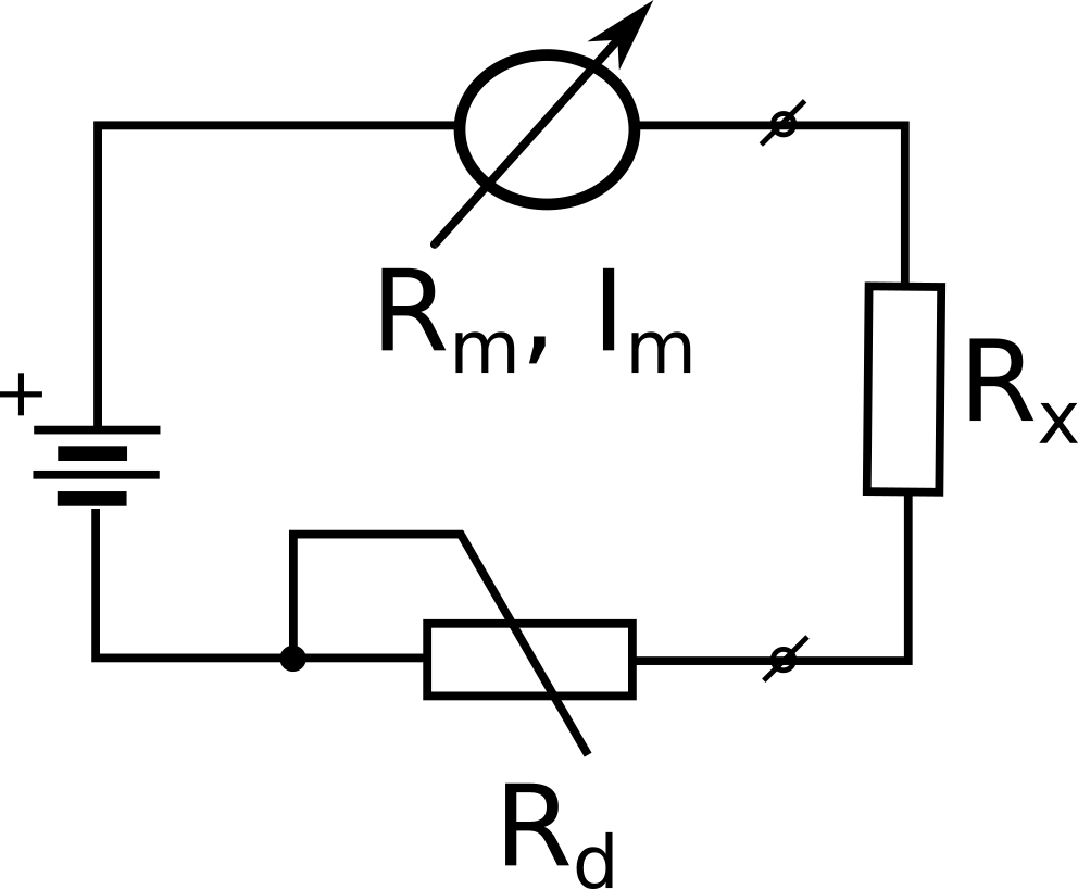
Its operation is described by the equation:
\(I = c_x \alpha_x = \frac{E} {R_x + R} \rightarrow \alpha_x = \frac {E} {c_x (R_x + R)}\)
where: \(R = R_d + R_m\).
Since \(R_d\) is selected in such a way that the highest current flows when the ohmmeter terminals are short-circuited (nominal current of the magnetoelectric meter, 1m), the coordinates of the points on the ohmmeter scale can be calculated from this. The scale of this ohmmeter is non-uniform and therefore the measurement error is characterized by giving the relative error of the normalized resistance \(R_x/R\). This error is the smallest for the center of the scale and increases as you approach the ends of the scale, and in addition, it depends on the accuracy class of the magnetoelectric meter used in the ohmmeter. Due to the aging of the battery supplying the ohmmeter, it is necessary before each resistance measurement reset it with terminals shorted.
When using analog multimeters, pay attention to the permissible position of the meter: vertical (marked "\(\bot\)") or horizontal.
More extensive analog multimeters include electronic amplifiers. Contrary to ordinary, i.e. electric, multimeters, these electronic multimeters require battery or mains power and therefore usually have an additional voltage switch. Electronic multimeters are much more sensitive than ordinary multimeters, so the input resistances of the voltmeter are much larger, but the concept of accuracy class does not apply then. The accuracy of the measurement is specified in the instruction manual of the device.
When measuring low DC and AC voltages, especially AC voltages and higher, an important issue is the grounding of one of the voltmeter terminals. In many electronic multimeters, as well as in oscilloscopes, generators and other electronic devices, one of the terminals of the instrument is connected to the housing and this terminal, called "ground", must be connected first to the circuit under test and disconnected last. In some devices (more expensive) it is possible to leave the so-called "Floating input", which means that both terminals of the device can be connected to points of a circuit with a potential other than zero ("ground"). But then the device usually has an additional third terminal to connect to the ground of the circuit under test.
Electronic devices are connected to similar devices or to the circuit under test by means of special shielded wires or coaxial cables with a suitable terminal. It is then important to connect both ends of such wires or cables correctly. Coaxial cables can have different endings: with plugs, i.e. banana terminals, with a special plug cooperating with the appropriate socket, e.g. in the BNC standard, or mixed ones: one end of the cable is terminated with plugs, and the other with a BNC plug.
When measuring high-frequency voltages (above 100 kHz, sometimes 10 kHz), special probes are used to measure voltages, which are connected directly to the tested circuit, while they are connected to the measuring device by a coaxial cable with a BNC plug. Such probes contain a high-frequency rectifier that outputs a direct voltage proportional to the peak value of the measured voltage. If they are connected to an instrument rated for rms sinusoidal voltages (which is usually the case), then for measurements of high-frequency voltages of other shapes, the obtained results must be properly interpreted in order to avoid systematic errors. HF measurement probes have a clearly distinguished ground end and a hot end.
Currently, the basic equipment of the electronic laboratory is a digital voltmeter. Its operation boils down to converting an analog quantity, i.e. a continuous quantity, into a discrete quantity. Such analog-to-digital conversion causes the measurand to be quantized: the instrument reacts identically to two measurand values within one quantization step, which determines the resolution of the voltmeter; for example, in the case of a 4-digit voltmeter with a range of 1 V, the resolution is 0.1 mV, so the voltmeter will give a value of 0.2 mV both when measuring voltage equal to 0.21 mV and for 0.23 mV. Thanks to such a high resolution, the digital voltmeter is very convenient for measurements that require registration of small changes in the tested voltage. However, displaying four significant figures on a digital gauge does not mean that this digital voltmeter measures voltage with an accuracy equal to resolution. In the measurement process, the measured quantity must also be compared with a standard of finite accuracy. Taking into account the fact that both the voltage pattern itself, the principle-dependent zero indicator circuit and other voltmeter electronics contribute their errors, it becomes obvious that measurement accuracy has no direct relationship to resolution. The accuracy of the measurement is specified by the manufacturer in the manual of the voltmeter.
Digital voltmeters have a very high input resistance (\(10 M \Omega\), and often \(100 M \Omega\)) and usually a floating input, i.e. three terminals on the front panel of the instrument, marked as follows:
• red - hot, sometimes also marked "HIGH",
• green - marked "LOW", usually connected with the "gnd" of the tested system or with a point of the system
connected to ground with a lower impedance than the hot terminal,
• black - marked "GROUND" or "EARTH" for distinguish, connected to the housing of the device to which the screen of the measurement cable is attached.
This method of connecting a voltmeter to the measured system is dictated by the need for reduction
external disturbances (induction of mains frequency voltages, higher frequency voltages, etc.), easily revealed due to the high input resistance of the digital voltmeter. It is often possible to additionally suppress interference by activating the filter with a switch marked as "FILTER".
Before starting the measurements, check zero indications; in voltmeters without automatic zero correction is done by a switch marked "ZERO".
Digital voltmeters make measurements cyclically with the frequency of several to several dozen measurements per second. Some have a built-in converter for alternating current voltages (measuring rectifier) and then when the switch labeled "AC" (for "alternating current") is turned on, the voltmeter measures alternating voltages, but in a limited frequency range, usually acoustic. Therefore, it is necessary to refer to the operating manual, which will also specify the value of the measured AC voltage to which the voltmeter responds and in what values it is marked (usually in the effective ones). In the laboratory, we will also use a digital multimeter and its operation follows many of the principles listed above.