Practice of working with electronic devices - theoretical Introduction
Main topics:
- magnetoelectric meter,
- designing and making own multi-range voltmeter
- soldering
The principle of operation of the magnetoelectric meter
The core of analog multimeters, also known as multimeters, is the magnetoelectric meter. Such a meter is characterized by the following parameters: nominal current Im, internal resistance Rm, current constant. Sometimes the critical resistance is also important, characterizing the conditions for reaching the steady state of the indication \( \alpha \) at the measured current i. They result from the simple theory of motion of the moving element presented below.
If a frame of dimensions a*b, containing z turns, is placed in a uniform magnetic field B and a current i flows through it (the frame then has a magnetic moment \( p_m = zabi = zSi \) or more precisely vector \( \vec{p_m} = z\vec{S}i \) ), then a torque of \( \vec{N} = \vec{p_m} x \vec{B} \) acts on it. Magnetoelectric meters have a magnetic circuit shaped in such a way (poles and a cylindrical core - see the figure below) that in any position of the frame with a very good approximation \( p_m \perp B \) and therefore \( N = p_mB = zabBi = ki \), where \( k = zabB \) is a constant for of a given meter.
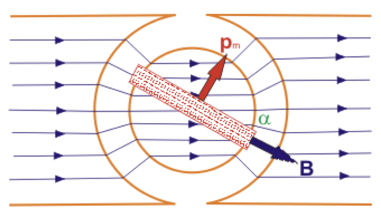
The frame is attached to a spiral spring with spring constant \( k_z \), attached with the other end to the meter housing and giving a return torque proportional to the twisting of the spring, i.e. to the frame deflection angle: \( N_z = - k_z\alpha \). \( N+N_z =0 \) is in equilibrium, which means that \( k_z \alpha=ki \), so \( \alpha=(k/k_z)I \) or by entering the current constant of the meter \( c_r = (k_z/k) \) we get that the angular deflection of the \( \alpha \) pointer is proportional to the current i: \( \alpha = I/c_r \).
During the movement of the moving element of the meter, it is additionally affected by the moment of braking forces, which is mainly the result of the phenomenon of electromagnetic induction, but also coming from the resistance of the coil in the air. This torque is proportional to the angular velocity \( d\alpha / dt = \omega: N_h = - k_h\omega \). On the other hand, the friction in the bearings gives a certain constant moment of force, which determines the accuracy of the meter's indications and is included in the accuracy class of the analog meter. In the case of electromagnetic attenuation, the coefficient \( k_h \) can be expressed by the meter constant \( k \) and by the external circuit resistance \( R_z \) and the meter resistance \( R_m \). During movement in the frame, an SEM \( \epsilon = - z (d\Phi / dt) = zabB (d\alpha / dt) = - k (d \alpha / dt) \) is induced, causing a current flow \( i_h = \epsilon / (Y_z + Y_m) \). This current causes a braking torque \( N_h= - ki_h \) proportional to the angular velocity: \( N_h = - k_h (d \alpha / dt) \), where \( k_h = k^2 / (R_z + R_m) \).
The dynamic equation of motion of the moving body of the multimiter has the following form:
\( N+N_Z + N_h = I \frac{d^2 \alpha}{dt^2} \)
that is:
\( ki – k_z \alpha – k_h \frac{d \alpha}{dt} = I \frac{d^2 \alpha}{dt^2} \)
where \( I \) is the moment of inertia of the moving body about the axis of rotation. This equation can be written in the standard form for a second-order differential equation with constant coefficients and known constraint, e.g. \( i(t) = I_m1(t) \):
\( \frac{d^2 \alpha}{dt^2} + 2 \beta \frac{d \alpha}{dt} + \omega_0^2 \alpha = \frac{ki}{I} \)
where \( \beta= k_h / 2I \) is the damping constant, \( \omega_0 =(k_z / I)^{1/2} \) is the undamped eigenvibration pulsation. The form of the solution to this differential equation depends on the relationship between the constants \( \beta \) and \( \omega_0 \) (see the figure below):
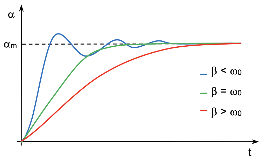
When \( \beta < \omega_0 \), the movement of the movable body is oscillatory, and when \( \beta > \omega_0 \), the movable element comes to a position fixed \( \alpha_m \) aperiodically. In the case of \( \beta = \omega_0 \), damping is critical and the moving body reaches equilibrium most quickly without oscillation. This is the most commonly desired case, although oscillating solutions with small oscillations are also used in practice.
Due to the dependence of \( \beta \) on \( R_z \) (through \( k_h \)), it is possible to select the operating conditions of the external circuit, ensuring critical or similar damping. A certain value of \( R_z\_kr \) corresponds to critical damping. If \( R_z > R{z\_kr} \), then \( k_h < k_{h\_kr} \), and therefore oscillations will occur. Otherwise, \( R_z < R_{z\_kr} \), the movement of the gauge pointer will be aperiodic. By observing the behavior of the meter pointer as it reaches the equilibrium position, the critical resistance of the meter in an adjustable resistance circuit can be estimated (note: critical resistance is often understood as the total resistance of the circuit, not just the resistance of the external part of the circuit).
Also, when constructing measuring instruments with a magnetoelectric meter, the results of the above analysis can be used to optimize the operation of the instrument in terms of the method of determining the indications (connection of parallel or series resistors).